Air valve facilitating monitoring working state

A technology of working status and air valve, applied in the direction of valve device, engine components, mechanical equipment, etc., can solve the problems of potential safety hazards, the inability to detect the air valve in time, and the inability to effectively feedback the opening and closing state of the air valve, etc., to achieve structural Simple, effective, and safety-enhancing effects

Inactive Publication Date: 2017-05-17
宁波市镇海百硕机械科技有限公司
View PDF0 Cites 0 Cited by
  • Summary
  • Abstract
  • Description
  • Claims
  • Application Information

AI Technical Summary

Problems solved by technology

The traditional air valve has two working states of open and closed, but it is simply controlled by the switch, but under certain conditions, it cannot effectively feedback the open and closed state of the air valve, which is very inconvenient, or the air valve fails under certain conditions And can not be found in time, causing safety hazards
The new intelligent ventilation system needs to display the opening and closing status of the air valve in the control system in real time, and send an alarm in time when there is a problem. The traditional air valve cannot meet the requirements

Method used


Image

  • Air valve facilitating monitoring working state
  • Air valve facilitating monitoring working state
  • Air valve facilitating monitoring working state

Examples


Embodiment Construction

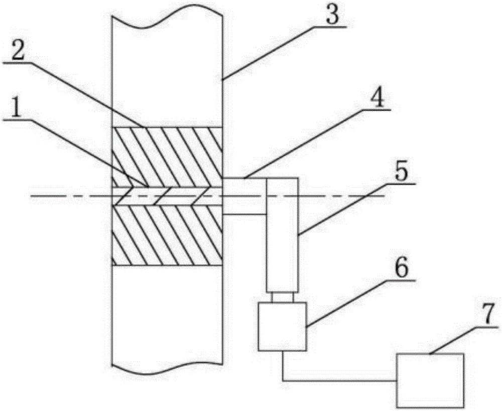
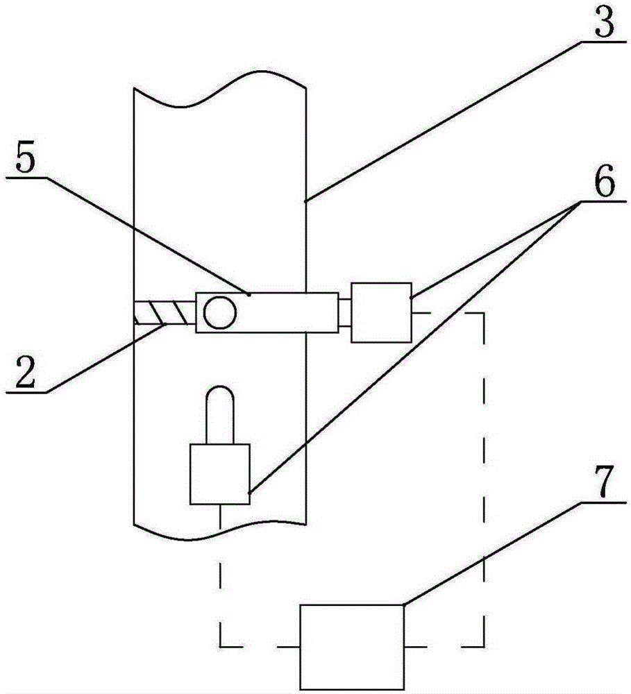
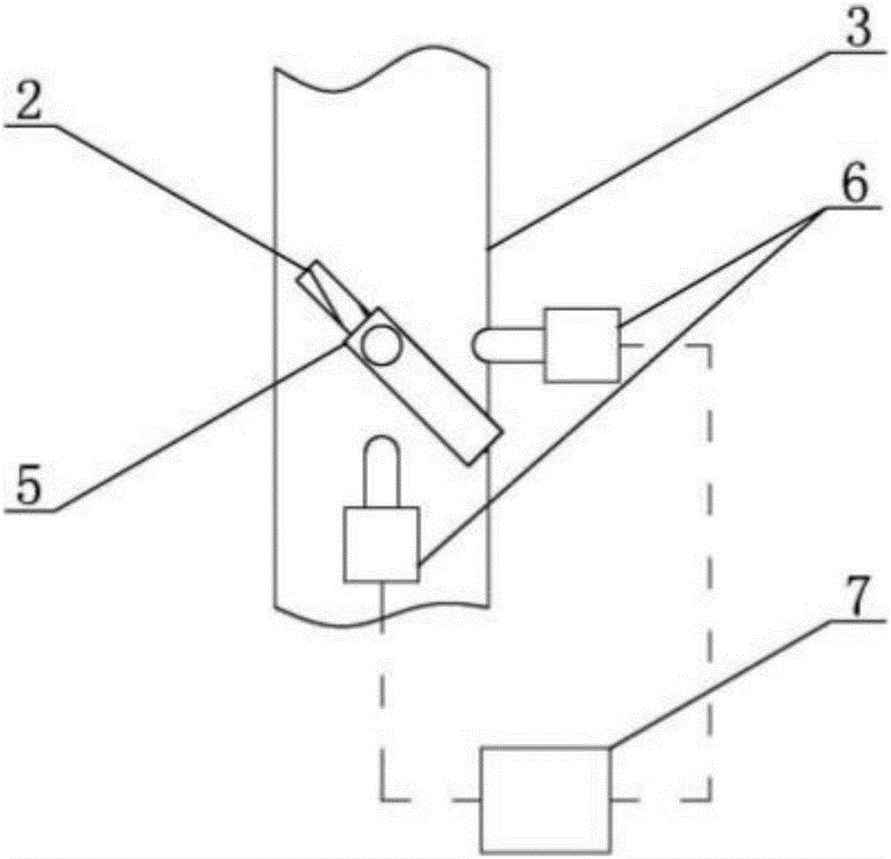
[0015] Such as figure 1 As shown, the air valve capable of monitoring the working state of the present invention includes a valve shaft 1 and a valve disc 2, the valve shaft 1 drives the valve disc 2 to rotate, the left and right ends of the valve shaft 1 are installed on the air duct 3, and are perpendicular to the air duct 3 installed in the air inlet direction. A protruding part 4 is processed on the end surface of the valve shaft 1 along the length direction of the valve shaft 1, and a sensing terminal 5 is connected to the protruding part 4, and the sensing terminal 5 is located outside the air duct. The sensing terminal 5 can rotate along the same rotation axis as the valve shaft 1 . Two vertically placed inductors 6 are arranged in the plane formed by the rotation of the sensing terminal 5 . Such as Figure 5 As shown, the sensor 6 includes a casing 9, and an inductive element 8 is arranged inside the casing 9. The inductive element 8 is a signal sensor capable of ge...


PUM


Abstract

The invention discloses an air valve facilitating monitoring a working state, relates to an air valve used in a ventilating duct, and aims at providing an air valve which achieves the effects that opening and closing states of the air valve can be monitored, the safety of the air valve is improved and the structure is simple. The air valve facilitating monitoring the working state comprises a valve shaft and a valve clack; the left end and the right end of the valve shaft are arranged on an air duct and the valve shaft is perpendicular to the air intake direction of the air duct; the side end face of the valve shaft is connected with an induction terminal; the induction terminal is located on the outer side of the air duct; the induction terminal and the valve shaft can rotate along the same rotating shaft, two perpendicularly arranged inductors are arranged in a plane formed by the rotation of the induction terminal; working surfaces of the two inductors face the axle center of the induction terminal when the induction terminal rotates; when the valve clack is in an opened state or in a closed state, the induction terminal can be in contact with the working face of one inductor or the working face of the other one inductor; and the two inductors are connected with a signal connector.

Description

technical field [0001] The invention relates to a damper, in particular to a damper capable of monitoring the opening and closing state. Background technique [0002] The air valve is used to adjust the air volume in the pipeline, and can also be used to adjust the mixing of fresh air and return air. The traditional air valve has two working states of open and closed, but it is simply controlled by the switch, but under certain conditions, it cannot effectively feedback the open and closed state of the air valve, which is very inconvenient, or the air valve fails under certain conditions If it cannot be detected in time, it will cause potential safety hazards. The new intelligent ventilation system needs to display the opening and closing status of the air valve in the control system in real time, and send an alarm in time when there is a problem. The traditional air valve cannot meet the requirements. Contents of the invention [0003] The technical problem to be solved...

Claims


Application Information

Patent Timeline
Patent Type & Authority Applications(China)
IPC IPC(8): F16K37/00
CPCF16K37/0041
Inventor 王海燕
Owner 宁波市镇海百硕机械科技有限公司
Why Eureka
Try Eureka