Air valve capable of monitoring work state

A working state, air valve technology, applied in valve devices, engine components, mechanical equipment, etc., can solve problems such as hidden safety hazards, air valves can not be found in time, air valves cannot meet requirements, etc., to improve safety, simple and effective structure Effect

Inactive Publication Date: 2016-03-16
BEIJING QIJIAYIJU TECHNOLOLGY CO LTD
View PDF8 Cites 1 Cited by
  • Summary
  • Abstract
  • Description
  • Claims
  • Application Information

AI Technical Summary

Problems solved by technology

The traditional air valve has two working states of open and closed, but it is simply controlled by the switch, but under certain conditions, it cannot effectively feedback the open and closed state of the air valve, which is very inconvenient, or the air valve fails under certain conditions And can not be found in time, causing safety hazards
The new intelligent ventilation system needs to display the opening and closing status of the air valve in the control system in real time, and send an alarm in time when there is a problem. The traditional air valve cannot meet the requirements

Method used


Image

  • Air valve capable of monitoring work state
  • Air valve capable of monitoring work state
  • Air valve capable of monitoring work state

Examples


Embodiment Construction

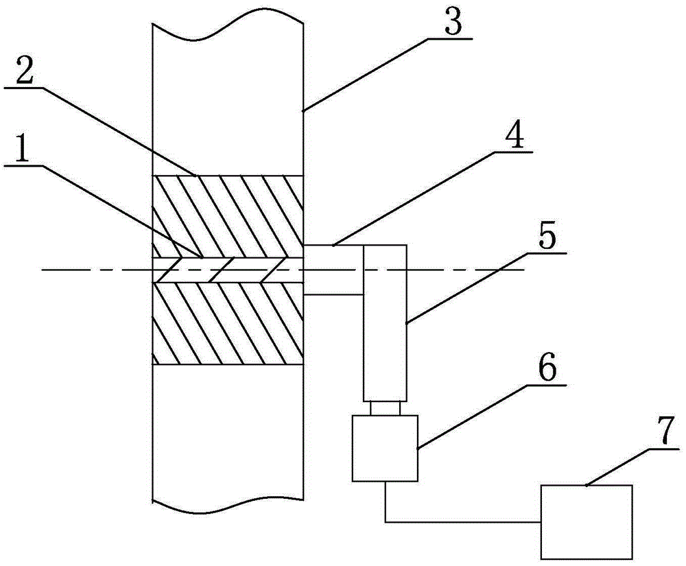
[0015] Such as figure 1 As shown, the air valve capable of monitoring the working state of the present invention includes a valve shaft 1 and a valve disc 2, the valve shaft 1 drives the valve disc 2 to rotate, the left and right ends of the valve shaft 1 are installed on the air duct 3, and are perpendicular to the air duct 3 installed in the air inlet direction. A protruding part 4 is processed on the end surface of the valve shaft 1 along the length direction of the valve shaft 1, and a sensing terminal 5 is connected to the protruding part 4, and the sensing terminal 5 is located outside the air duct. The sensing terminal 5 can rotate along the same rotation axis as the valve shaft 1 . Two vertically placed inductors 6 are arranged in the plane formed by the rotation of the sensing terminal 5 . Such as Figure 5 As shown, the sensor 6 includes a casing 9, and an inductive element 8 is arranged inside the casing 9. The inductive element 8 is a signal sensor capable of ge...


PUM


Abstract

The invention provides an air valve capable of monitoring work state and relates to an air valve used in a ventilation pipeline. The objective is to provide an air valve which can monitor the open and close states of the air valve and improve the safety of the air valve and is simple in structure. The air valve capable of monitoring work state comprises a valve shaft and a valve clack, wherein the left and right two ends of the valve shaft are mounted on an air duct, and the valve shaft is mounted perpendicular to the air inlet direction of the air duct; an induction terminal is connected to the side end surface of the valve shaft, the induction terminal is positioned on the outer side of the air duct, and the induction terminal can rotate along the same rotating shaft with the valve shaft; two sensors perpendicularly placed are arranged in a plane formed by the rotating of the induction terminal, and the work surfaces of both of the two sensors face an axis of the induction terminal during rotating; and when the valve clack is in open and close states, the induction terminal can be in contact with the work surface of one of the sensors, and the sensors are both connected with a signal connector.

Description

technical field [0001] The invention relates to a damper, in particular to a damper capable of monitoring the opening and closing state. Background technique [0002] The air valve is used to adjust the air volume in the pipeline, and can also be used to adjust the mixing of fresh air and return air. The traditional air valve has two working states of open and closed, but it is simply controlled by the switch, but under certain conditions, it cannot effectively feedback the open and closed state of the air valve, which is very inconvenient, or the air valve fails under certain conditions If it cannot be detected in time, it will cause potential safety hazards. The new intelligent ventilation system needs to display the opening and closing status of the air valve in the control system in real time, and send an alarm in time when there is a problem. The traditional air valve cannot meet the requirements. Contents of the invention [0003] The technical problem to be solved...

Claims


Application Information

Patent Timeline
Patent Type & Authority Applications(China)
IPC IPC(8): F16K37/00
CPCF16K37/00F16K37/0041
Inventor 查激星罗帅
Owner BEIJING QIJIAYIJU TECHNOLOLGY CO LTD
Why Eureka
Try Eureka