A fault prediction method and device

A failure prediction and failure technology, applied in the computer field, can solve the problems of unstable prediction result accuracy, low prediction efficiency and high labor cost, and achieve the effect of reducing failure risk and harm, saving labor cost and high prediction efficiency.

Active Publication Date: 2020-01-31
NEUSOFT CORP
View PDF7 Cites 0 Cited by
  • Summary
  • Abstract
  • Description
  • Claims
  • Application Information

AI Technical Summary

Problems solved by technology

[0005] In view of this, the present invention provides a fault prediction method and device, which can solve the problems of high labor cost, unstable prediction result accuracy and low prediction efficiency in the prior art

Method used


Image

  • A fault prediction method and device
  • A fault prediction method and device
  • A fault prediction method and device

Examples


Embodiment Construction

[0056] In order to enable those skilled in the art to better understand the solutions of the present invention, the technical solutions in the embodiments of the present invention will be clearly and completely described below in conjunction with the drawings in the embodiments of the present invention. Obviously, the described embodiments are only It is a part of embodiments of the present invention, but not all embodiments. Based on the embodiments of the present invention, all other embodiments obtained by persons of ordinary skill in the art without making creative efforts belong to the protection scope of the present invention.

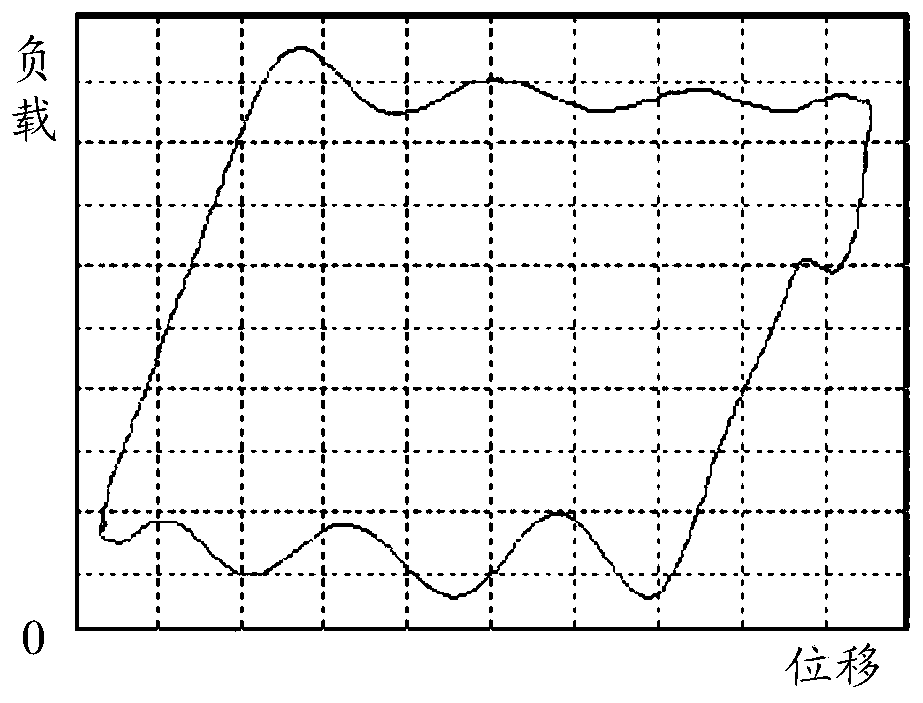
[0057] In order to facilitate the understanding of the specific solutions provided by the embodiments of the present invention, combined with figure 1 The dynamometer diagram shown as an example introduces the method for generating the dynamometer diagram involved in the embodiment of the present invention. Take the dynamometer diagram of the pu...


PUM


Abstract

The embodiment of the invention discloses a fault prediction method. The failure prediction method comprises the following steps that an indicator diagram of monitored equipment is obtained, and the indicator diagram to be predicted is obtained; the indicator diagram to be predicted is matched with an indicator diagram corresponding to each sample in a sample set obtained in advance, and the matching degree between the indicator diagram to be predicted and the indicator diagram corresponding to each sample is obtained, wherein each sample in the sample set corresponds to a fault working state; the maximum matching degree is obtained from the matching degrees; and the fault working state corresponding to the sample with the maximum matching degree is determined as a predictive fault of the monitored equipment. According to the fault prediction method provided by the embodiment of the invention, advance prediction of the fault of the monitored equipment can be realized, the result of the fault prediction is accurate, the prediction efficiency is high, the risk and harm of the fault are reduced, the manual comparison of the indicator diagrams is not needed, and thus labor cost is saved.

Description

technical field [0001] The invention relates to the field of computer technology, in particular to a fault prediction method and device. Background technique [0002] The dynamometer diagram is a closed curve used to reflect the changing law of the suspension point load of the pumping unit with the suspension point displacement. Generally, the suspension point displacement is taken as the abscissa and the suspension point load is the ordinate, showing the specific characteristics of the tested equipment. working status. In the actual oil production work in the oil field, the working condition of the pumping unit and the failure reasons of the pumping unit and the oil well are often judged by analyzing the dynamometer diagram. [0003] In the oil extraction industry, since the oil field is usually located in an area far away from the population and the geographical environment is relatively complex, once the oil well or the pumping unit fails, the staff cannot find the probl...

Claims


Application Information

Patent Timeline
Patent Type & Authority Patents(China)
IPC IPC(8): E21B47/008G06Q10/04
CPCE21B47/008G06Q10/04
Inventor 周方超
Owner NEUSOFT CORP
Why Eureka
Try Eureka