
Synchronous feeding device and sewing machine

A technology of feeding device and feeding dog, which is applied in the direction of sewing machine components, sewing machine control devices, cloth feeding mechanism, etc., can solve the problems such as the complicated structure of driving the mop wheel, and achieve the effects of reducing costs, ensuring aesthetics, and improving efficiency

Active Publication Date: 2017-05-17
JACK SEWING MASCH CO LTD
View PDF4 Cites 7 Cited by
  • Summary
  • Abstract
  • Description
  • Claims
  • Application Information

AI Technical Summary

Problems solved by technology

[0004] Although the above-mentioned structure solves the defects caused by the manual pulling of cloth by the existing operators, there are defects such as the complicated structure for driving the mop wheel and the need to set up an independent power source to drive the tug wheel.

Method used


Image

  • Synchronous feeding device and sewing machine
  • Synchronous feeding device and sewing machine
  • Synchronous feeding device and sewing machine

Examples


Embodiment Construction

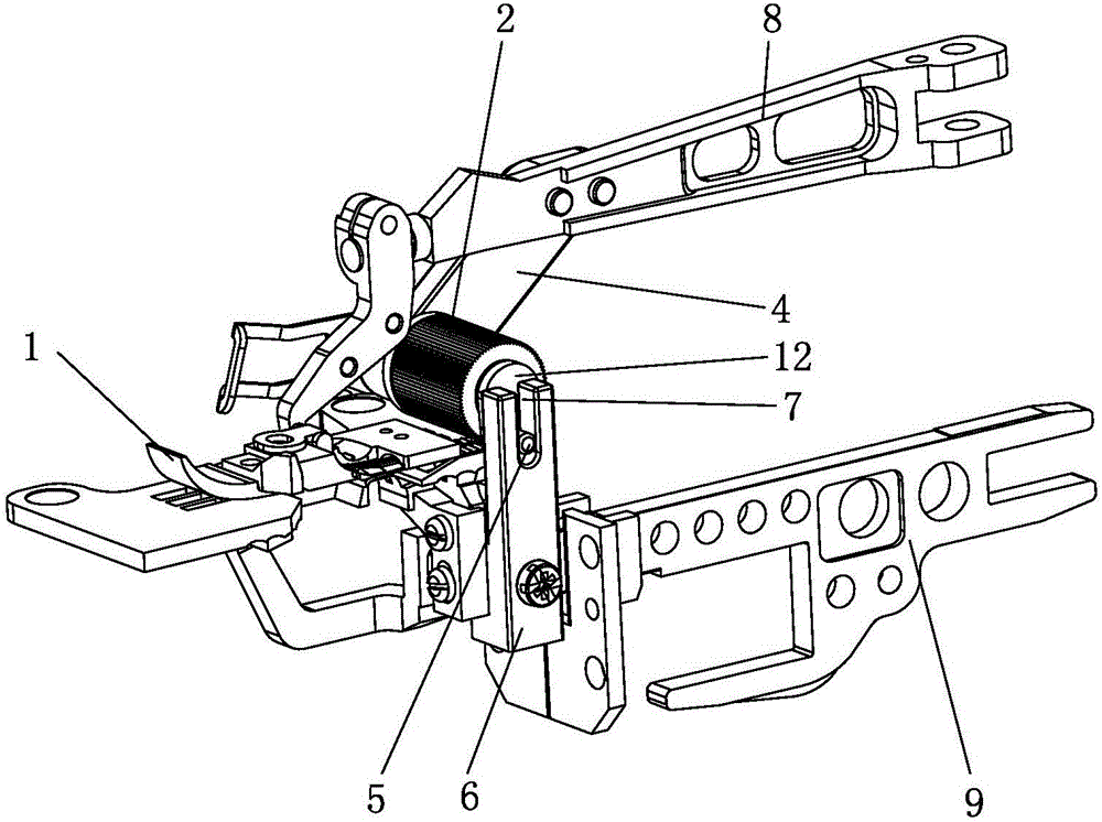
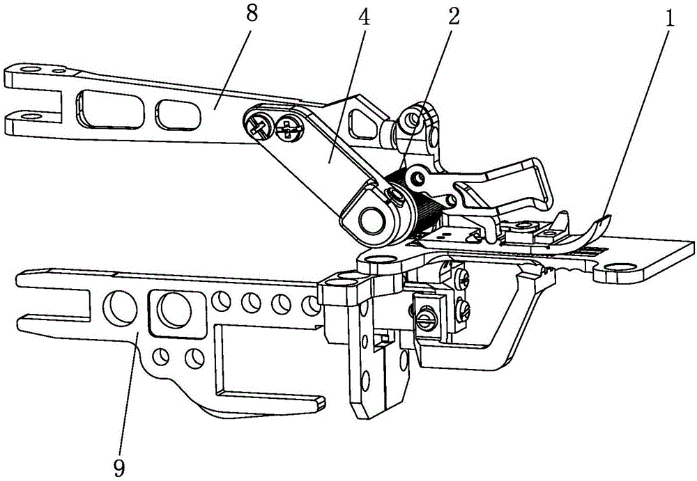
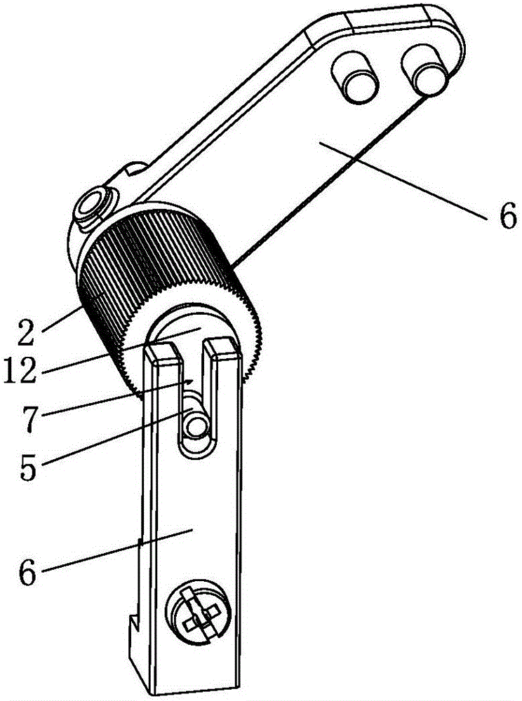
[0021] The following are specific embodiments of the present invention and in conjunction with the attached Figure 1-4 , to further describe the technical solutions of the present invention, but the present invention is not limited to these embodiments.

[0022] Such as figure 1 , 2 As shown in , 3, a synchronous feeding device includes a rear tug wheel 2 arranged at the rear end of the presser foot 1, the rear tug wheel 2 is arranged on the driving rod 3, and the rear tug wheel 2 rotates in one direction around the driving rod 3, and the driving rod 3 One end is connected to one end of the tugboat frame 4, and the other end is provided with a connecting pin 5 eccentrically arranged with the driving rod 3, and the connecting pin 5 is arranged in the strip groove 7 of the driving frame 6 to realize the intermittent one-way rotation of the rear tugboat 2 , the other end of the tug wheel frame 4 is connected on the presser foot arm 8, and the driving frame 6 is fixed on the fe...


PUM


Abstract

The invention belongs to the technical field of sewing equipment and particularly relates to a synchronous feeding device and a sewing machine. The synchronous feeding device includes a rear dragging wheel arranged at the rear end of a presser foot, the rear dragging wheel is arranged on a driving rod and rotates around the driving rod in one direction, one end of the driving rod is connected with one end of a dragging wheel frame, the other end of the driving rod is provided with a connecting pin which is eccentrically arranged with the driving rod, the connecting pin is arranged in a strip-shaped groove of a driving frame to achieve intermittent one-way rotation of the rear dragging wheel, the other end of the dragging wheel frame is connected with the presser foot, the driving frame is fixed on a feeding tooth frame, the eccentric radius of the driving rod is larger than the long axis radius of the elliptical motion track of the feeding tooth frame. The rear dragging wheel, a presser foot arm and the presser foot move up and down together, material feeding steps of an operator are reduced, no additional independent power source driving cloth-dragging wheel is needed, the cost is reduced and the efficiency is improved.

Description

technical field [0001] The invention belongs to the technical field of sewing equipment, in particular to a synchronous feeding device and a sewing machine. Background technique [0002] Existing overlock sewing machine all is to finish the process of whole sewing cloth feeding by operator's hand pulling cloth. In the existing sewing operation process, due to the instability of the operator's manual pulling of the cloth, there is a deviation in the speed of the cloth. Therefore, the speed of the cloth pulling process will not match the speed of the teeth feeding of the sewing machine, and the pulling will be slow. The thread cutter on the sewing machine has the risk of cutting the cloth, which will cause deformation of the cloth and stitches, and affect the aesthetics of the stitches. [0003] For above-mentioned phenomenon, my country's utility model patent (notification number CN 20341173U) discloses a kind of synchronous feeding device of sewing machine. The synchronous...

Claims


Application Information

Patent Timeline
Patent Type & Authority Applications(China)
IPC IPC(8): D05B27/14D05B69/02D05B29/06D05B27/24
Inventor 朱赛瑞吴平徐永明王路龙
Owner JACK SEWING MASCH CO LTD
Learn More