
Sludge dryer

A sludge drying and fan technology, applied in water/sludge/sewage treatment, dehydration/drying/concentrated sludge treatment, water/sewage treatment, etc., can solve problems such as ineffective drying of biological sludge, and achieve rapid The effect of sludge dewatering and low energy consumption

Pending Publication Date: 2017-05-17
NANJING KING FRIEND BIOCHEM PHARMA CO LTD
View PDF0 Cites 0 Cited by
  • Summary
  • Abstract
  • Description
  • Claims
  • Application Information

AI Technical Summary

Problems solved by technology

[0003] The purpose of the present invention is to provide a sludge dryer to solve the technical problem that the sludge dryer in the prior art cannot effectively dry biological sludge with high moisture content

Method used


Image

  • Sludge dryer

Examples


Embodiment Construction

[0021] The present invention will be described in detail below in conjunction with the accompanying drawings and specific embodiments.

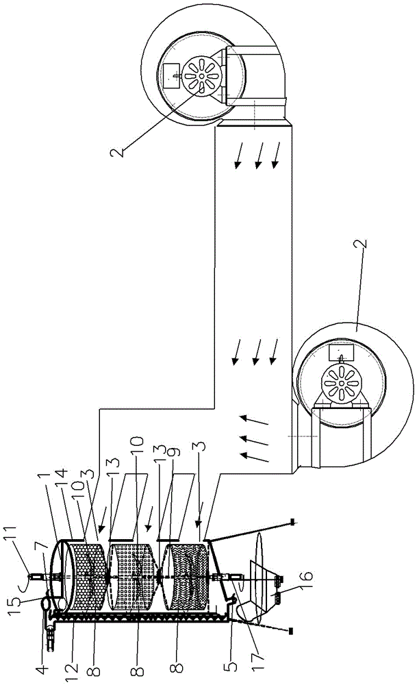
[0022] An embodiment of the present invention is figure 1 As shown, the sludge dryer in this embodiment includes a sleeve 1 with a vertical axis and a fan 2 for providing airflow to the inside of the sleeve. The wall of the sleeve 1 is provided with an air inlet 3, and the top of the sleeve is provided with an air inlet. The bottom of the material port 4 and the bottom are provided with a discharge port 5, the bottom of the sleeve 1 is an obliquely downward closing structure, the discharge port 5 is arranged at the bottom end of the closing structure, and the bottom of the discharge port 5 is provided with Receive hopper 16. The inlet 6 is provided with an air outlet 7, and the air outlet 7 is provided with a filter screen 15, and the mesh of the filter screen 15 is 100 mesh. The sleeve 1 is provided with a thermal insulation jacket 14, and...


PUM


Abstract

The invention discloses a sludge dryer. The sludge dryer comprises a sleeve with the axis arranged vertically and a fan for supplying airflow to the interior of the sleeve, wherein an air inlet is formed in the wall surface of the sleeve, a feeding port is formed in the top of the sleeve, a discharging port is formed in the bottom of the sleeve, an exhaust port is formed in the feeding port, two or more rolling barrels are arranged in the sleeve and connected together vertically and adopt a top opening structure, axes of the rolling barrels are overlapped with the axis of the sleeve, mesh holes are formed in the bottom surface of the side surface of each rolling barrel, and the size of the mesh holes in the rolling barrels is reduced from top to bottom sequentially; a rotating shaft penetrating the centers of the rolling barrels is arranged on a central shaft of the sleeve, crushing blades are arranged at the parts, located in the rolling barrels, of the rotating shaft, a blade motor for driving the rotating shaft to rotate is arranged above the sleeve, a rolling barrel motor for driving the rolling barrel to rotate is arranged below the sleeve, the rotating shaft and the rolling barrel are opposite in rolling direction, a vertical screw conveyor is arranged in a position, close to the wall surface, in the sleeve, the upper end of the screw conveyor is located at the feeding port, and the lower end of the screw conveyor is lower than the bottom of the rolling barrel at the bottom.

Description

technical field [0001] The invention relates to a sludge dryer, which belongs to the technical field of sludge treatment equipment. Background technique [0002] With the strengthening of the country's economic strength and the improvement of national environmental protection awareness, the urban sewage treatment industry has developed rapidly, and the output of urban sludge has increased day by day. People are increasingly concerned about the disposal and development of sludge. The drying treatment of sludge makes it possible for sludge to be used in agriculture, used as fuel, incinerated, and even to reduce landfill sites. The sludge dryer in the prior art is an indirect heating low-speed stirring dryer, which adopts a horizontal structure, and a rotating shaft is arranged inside the shell, and a stirring blade is arranged on the rotating shaft, which will enter the air during the heating and stirring process. The sludge in the shell is dried to remove the moisture in the...

Claims


Application Information

Patent Timeline
IPC IPC(8): C02F11/12
CPCC02F11/12C02F2201/002
Inventor 唐咏群黄锡伟王春华孙大春王志倩
Owner NANJING KING FRIEND BIOCHEM PHARMA CO LTD
Learn More