Light bridge crane guided by horizontal wheel opposite angles

A technology of bridge cranes and horizontal wheels, which is applied in the direction of walking bridge cranes, cranes, and traveling mechanisms, and can solve the problems of heavy weight, many links, and large space occupied by the operating mechanism.

Inactive Publication Date: 2017-05-17
李相迎 +6
View PDF3 Cites 0 Cited by
  • Summary
  • Abstract
  • Description
  • Claims
  • Application Information

AI Technical Summary

Problems solved by technology

[0002] The bridge crane is a lifting device that is placed horizontally over the workshop, warehouse and stockyard for material lifting. The bridge frame of the bridge crane runs longitudinally along the tracks laid on the elevated sides on both sides, and the lifting trolley runs along the tracks laid on the bridge frame. Horizontal operation constitutes a rectangular working range, which can make full use of the space under the bridge frame to lift materials without being hindered by ground equipment. Therefore, bridge cranes are the most widely used and most numerous hoisting machinery; carts The operating mechanism is one of the most basic mechanisms in the crane. The traditional cart operating mechanism is mostly arranged horizontally. The motor drives the reducer through the brake, coupling and transmission shaft, and the output shaft of the reducer drives the wheel group through the full-tooth coupling. , to realize the translational movement of the crane. The motor, reducer and brake are fixed on the walking platform through the base. Both the brake and the brake are fixed on the walking platform through the base. In order to ensure the stable transmission of the mechanism, the walking platform is required to have better rigidity and more accessories, so the weight of the whole machine is heavier; There are wheel rim guides, horizontal wheel guides and grooved guides. Most of the carts run because of irregular track gauge, wheel deflection, unequal wheel diameters, and uneven wheel pressure. Lateral sliding produces lateral force, resulting in rail gnawing. Therefore, it is very necessary to find a suitable guiding method to solve the phenomenon of gnawing rails.

Method used


Image

  • Light bridge crane guided by horizontal wheel opposite angles
  • Light bridge crane guided by horizontal wheel opposite angles
  • Light bridge crane guided by horizontal wheel opposite angles

Examples


Embodiment 1

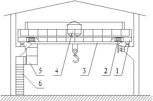
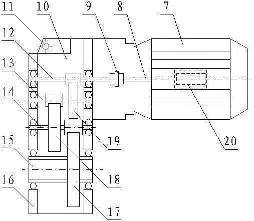
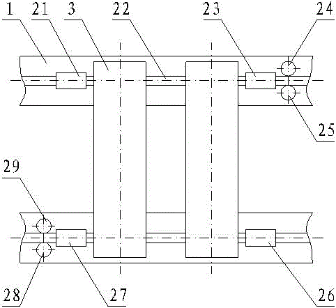
[0019] Such as figure 1 , figure 2 and image 3 As shown, a portable bridge crane with horizontal wheel diagonal guidance, it includes a main girder 3, the two ends of the main girder 3 are respectively connected with end beams 1, and the main girder 3 is close to the left end girder 1 A control room 5 is provided below the end beam 1, a ladder 6 is connected to the left side of the end beam 1, a lifting trolley 4 is provided on the upper side of the main beam 3, and large The cart running mechanism 2, the cart running mechanism 2 includes a motor 7, the lower end of the motor 7 is fixed on the main beam 3 through the motor support 20, the left end of the motor 7 is welded on the box body 10, the The box 10 is fixed on the main beam 3 through the moment support hole 11, the motor 7 is connected to the coupling 9 through the motor output shaft 8, and the coupling 9 is connected to the gear A19 through the gear shaft A12, so The gear A19 is connected to the gear B18 through ...

Embodiment 2

[0022] Such as figure 1 , figure 2 and image 3 As shown, a portable bridge crane with horizontal wheel diagonal guidance, it includes a main girder 3, the two ends of the main girder 3 are respectively connected with end beams 1, and the main girder 3 is close to the left end girder 1 A control room 5 is provided below the end beam 1, a ladder 6 is connected to the left side of the end beam 1, a lifting trolley 4 is provided on the upper side of the main beam 3, and large The cart running mechanism 2, the cart running mechanism 2 includes a motor 7, the lower end of the motor 7 is fixed on the main beam 3 through the motor support 20, the left end of the motor 7 is welded on the box body 10, the The box 10 is fixed on the main beam 3 through the moment support hole 11, the motor 7 is connected to the coupling 9 through the motor output shaft 8, and the coupling 9 is connected to the gear A19 through the gear shaft A12, so The gear A19 is connected to the gear B18 through ...


PUM


Abstract

The invention relates a light bridge crane guided by horizontal wheel opposite angles. The light bridge crane comprises a main beam; large trolley travelling mechanisms are installed at the left end and the right end of the upper side surface of the main beam correspondingly; each large trolley travelling mechanism comprises an electromotor, wherein the electromotor is connected with a coupling through an electromotor output shaft, the coupling is connected with a gear A through a gear shaft A, the gear A is connected with a gear B through a gear shaft B, the gear B is connected with a gear C through a gear shaft C, and the gear C is connected with a low speed shaft; the low speed shafts are installed on a large trolley wheel B and a large trolley wheel D in a sleeving mode correspondingly; a horizontal guide pulley A and a horizontal guide pulley B are installed on the outer side of the large trolley wheel B and on the two sides of a rail correspondingly; and a horizontal guide pulley C and a horizontal guide pulley D are installed on the outer side of the large trolley wheel D and on the two sides of the rail correspondingly. The light bridge crane guided by the horizontal wheel opposite angles has the advantages that the structure is simple, transmission efficiency is high, the integration level is high, the size is small, the weight is light, and rail gnawing can be effectively avoided.

Description

technical field [0001] The invention belongs to the field of engineering machinery, in particular to a bridge crane, in particular to a portable bridge crane with horizontal wheels and diagonal guidance. Background technique [0002] The bridge crane is a lifting device that is horizontally placed over the workshop, warehouse and stockyard for material lifting. The bridge frame of the bridge crane runs longitudinally along the tracks laid on the elevated sides on both sides, and the lifting trolley runs along the tracks laid on the bridge frame. Horizontal operation constitutes a rectangular working range, which can make full use of the space under the bridge frame to lift materials without being hindered by ground equipment. Therefore, bridge cranes are the most widely used and most numerous lifting machinery; The operating mechanism is one of the most basic mechanisms in the crane. The traditional cart operating mechanism is mostly arranged horizontally. The motor drives t...

Claims


Application Information

Patent Timeline
Patent Type & Authority Applications(China)
IPC IPC(8): B66C17/00B66C9/14B66C9/08
CPCB66C17/00B66C9/08B66C9/14
Inventor 李相迎刘国彬常守祥王志伟冯自勇杨云霞王志民
Owner 李相迎
Why Eureka
Try Eureka