A method for correcting yarn movement at a working point of a textile machine producing cross wound bobbins

A technology for cross-winding bobbins and textile machines. It is used in thin material handling, conveying filamentous materials, transportation and packaging, and can solve problems such as failures and damage to textile machine parts.

Active Publication Date: 2017-05-17
SAURER SPINNING SOLUTIONS GMBH & CO KG
View PDF9 Cites 4 Cited by
  • Summary
  • Abstract
  • Description
  • Claims
  • Application Information

AI Technical Summary

Problems solved by technology

When continuing to run automatically, the yarn may not be able to autonomously return to the yarn travel path, whereby a yarn traveling in a section outside the yarn travel path may cause friction-dependent malfunctions, possibly accompanied by damage to textile machine components

Method used


Image

  • A method for correcting yarn movement at a working point of a textile machine producing cross wound bobbins
  • A method for correcting yarn movement at a working point of a textile machine producing cross wound bobbins
  • A method for correcting yarn movement at a working point of a textile machine producing cross wound bobbins

Examples


Embodiment Construction

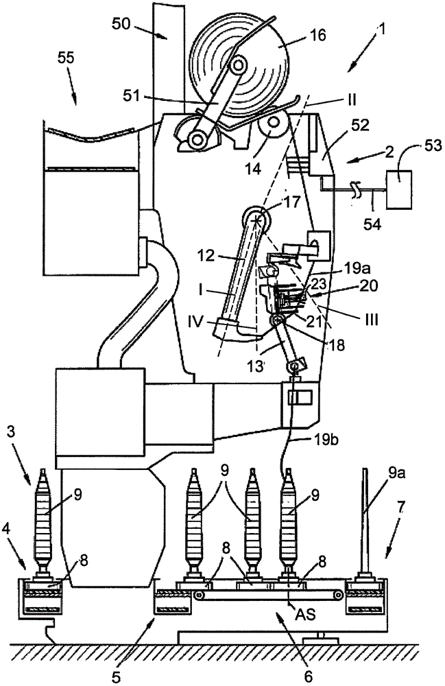
[0023] figure 1 A schematic side view of a station 2 of a textile machine, here in the form of an automatic cross-winding winder 1 , according to one embodiment is shown.

[0024] As is known, such an automatic cross-winding winder 1 has a plurality of identical stations 2 , here winding stations 2 , between its (not shown) end supports. On the winding station 2, the tube 9 loaded as an unwinding bobbin is rewound into a large package cross-wound bobbin 16 forming a winding bobbin.

[0025] The winding station 2 has a yarn splicer 10 set back slightly with respect to the normal yarn travel path for the piecing connection of a so-called top yarn 19 a from a cross-wound bobbin 16 with a so-called ground yarn 19 b from a bobbin 9 . Such a splicing connection may be necessary, for example, after providing a new bobbin 9, after a yarn break, or after a controlled so-called clearing cut-off in order to remove yarn defects.

[0026]The basic mode of operation of such an automatic c...


PUM


Abstract

The invention relates to a method (100) for correcting yarn movement at a working point (2) of a textile machine (1) producing cross wound bobbins. The working point (2) comprises a device for extracting yarn (19), a device (50) for winding the extracted yarn (19) into the cross wound bobbins (16), and a yarn catcher (12) arranged between the extracting device and the winding device (50) and capable of swinging to different positions. The yarn catcher (12) is at least used for receiving and transmitting the received yarn heads. The yarn catcher (12) is provided with a clamping structure used for clamping yarn sections. The method (100) includes a first step (110) of allowing the yarn catcher (12) to swing to a primary position (I) where the clamping structure is opposite to yarn moving between the extracting device and the winding device. The method (100) is characterized in that the method includes a second step (120) of allowing the yarn catcher (12) clamping the yarn (19) to swing from the primary position (I) to an extracting position (III) spaced from the primary position, and a third step (130) of releasing the yarn (19) bearing tension at a releasing position (IV).

Description

technical field [0001] The invention relates to a method according to the invention for correcting the yarn movement at a station of a textile machine for manufacturing cross-wound bobbins. Background technique [0002] Such textile machines, such as cross-winding winders and open-end rotor spinning machines, have long been known and are described in detail in numerous patent documents (eg documents DE10224080A1 and DE102009030802A1). [0003] What these textile machine types have in common is that the supplied yarn is wound into bobbins in the area of ​​the winding device, where, for example, in the event of a yarn break, the broken yarn end is caught by a yarn catcher and passed on In order to subsequently manufacture the yarn that moves from the yarn withdrawal device to the yarn winding device. For connecting disconnected yarns, cross-winding winders are usually equipped with yarn splicers, while open-end rotor spinning machines are equipped with piecing devices, which ...

Claims


Application Information

Patent Timeline
Patent Type & Authority Applications(China)
IPC IPC(8): B65H67/08B65H69/06
CPCB65H67/081B65H69/06B65H2701/31
Inventor M·蒙德O·内比格S·斯查顿
Owner SAURER SPINNING SOLUTIONS GMBH & CO KG
Why Eureka
Try Eureka