
Motor train unit head train passive safety protection device

A protective device and passive safety technology, applied in traction devices, railway vehicle wheel guards/buffers, transportation and packaging, etc., can solve unreasonable local strength requirements of the car body, large ratio of peak force to average force, and energy absorption The problem of low energy absorption efficiency of the device can solve the problems of low or insufficient absorption efficiency, guarantee the safety of life and property, and reduce maintenance costs

Inactive Publication Date: 2017-05-17
CRRC CHANGCHUN RAILWAY VEHICLES CO LTD
View PDF9 Cites 14 Cited by
  • Summary
  • Abstract
  • Description
  • Claims
  • Application Information

AI Technical Summary

Problems solved by technology

[0003] At present, rail transit vehicles usually arrange energy-absorbing devices at both ends of the train, but due to the various forms and arrangements of absorbing devices, on the one hand, due to the large ratio of peak force to average force of some forms of energy-absorbing devices , The impact load fluctuates greatly, resulting in low overall energy absorption efficiency of the energy absorbing device; on the other hand, due to the unreasonable structural layout and design, higher requirements are put forward for the car body, and even the load of some buffer energy absorbing devices is too concentrated , the local car body strength requirements for its installation parts are very high, and it is difficult to meet the strength bearing requirements in car body design
For example: commonly used expansion tube energy absorption, shrink tube energy absorption, cutting energy absorption, vehicle end structure energy absorption (such as anti-collision column energy absorption, etc.) all have unreasonable energy distribution of energy absorption components and low efficiency of collision energy absorption. High, unreasonable requirements for the local strength of the car body, etc.

Method used


Image

  • Motor train unit head train passive safety protection device
  • Motor train unit head train passive safety protection device
  • Motor train unit head train passive safety protection device

Examples


Embodiment Construction

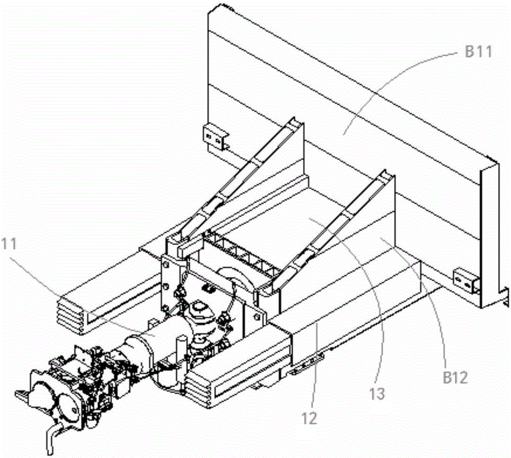
[0032] Such as figure 1 , 2 As shown: the protection device of the present invention is installed on the front end of the anti-collision plate B11 of the head car body B, and the protection device is installed on the head car body B as a structure that can be flexibly disassembled and replaced. In the event of an accident, the protective device is responsible for collision energy absorption. During the whole process, it should ensure that the body B of the leading vehicle does not undergo severe crushing and deformation, that is, ensure the living space of passengers. The protection device is composed of a coupler buffer assembly 11, an anti-climber assembly 12, and a main energy absorber assembly 13; wherein, the main energy absorber assembly 13 is installed on the front end of the anti-collision plate B11 of the body B of the leading vehicle; The coupler buffer assembly 11 is arranged in front of the main energy absorber assembly 13, and is installed on the two side guard p...


PUM


Abstract

The invention relates to a motor train unit head train passive safety protection device which comprises coupler and draft gear components, anti-creeper components and a main energy absorber component, wherein the main energy absorber component is mounted at the front end of a head train body bumper rail, the coupler and draft gear components are arranged in the front of the main energy absorber component and mounted on guard plates of two sides of the front end of the head train body bumper rail, and the anti-creeper components are arranged on two sides of the guard plates. The protection device is simple in structure, reasonable in layout and high in reliability, energy can be sufficiently and reasonably absorbed when a train collides, life and property safety of passengers is guaranteed, and structural integrality of a rail train body is furthest maintained.

Description

technical field [0001] The invention belongs to the technical field of anti-climbing and energy-absorbing passive safety protection for high-speed EMUs, and in particular relates to a passive safety protection device for a head car of a high-speed train. Background technique [0002] With the rapid development of my country's rail transit construction, while travel is more convenient, the harm caused by accidents is also increasing. While improving the reliability of active control, the passive safety of rail buses has gradually become the focus of attention. Since the leading car has the greatest impact force when a rail train collides, and the following cars decrease step by step, therefore, considering the energy absorption requirements of trains and the actual energy absorption method, an absorbing device with more energy is usually arranged on the leading car of the train. [0003] At present, rail transit vehicles usually arrange energy absorbing devices at both ends o...

Claims


Application Information

Patent Timeline
Patent Type & Authority Applications(China)
IPC IPC(8): B61F19/04B61G9/04B61G11/16
CPCB61F19/04B61G9/04B61G11/16
Inventor 姜士鸿闵韩琴丛立新李国良
Owner CRRC CHANGCHUN RAILWAY VEHICLES CO LTD
Learn More