Relief valve for fuel supply system and method for manufacturing such a valve

A fuel supply system, overflow valve technology, applied in the direction of the charging system, pumping device components for elastic fluid, liquid fuel feeder, etc., can solve the problem of expensive mechanical chip removal operations, long processing time, waste Material and other issues, to achieve the effects of reduced leakage, prevention of accumulation, and low manufacturing costs

Active Publication Date: 2019-08-30
ROBERT BOSCH GMBH
View PDF4 Cites 0 Cited by
  • Summary
  • Abstract
  • Description
  • Claims
  • Application Information

AI Technical Summary

Problems solved by technology

[0004] The disadvantage of the prior art is that the valves produced thereby are expensive and require long processing times
In fact, during machining, 60% of the material of a solid cylinder is removed, resulting in wasted material
Furthermore, the aforementioned mechanical chip removal operations are expensive

Method used


Image

  • Relief valve for fuel supply system and method for manufacturing such a valve
  • Relief valve for fuel supply system and method for manufacturing such a valve
  • Relief valve for fuel supply system and method for manufacturing such a valve

Examples


Embodiment Construction

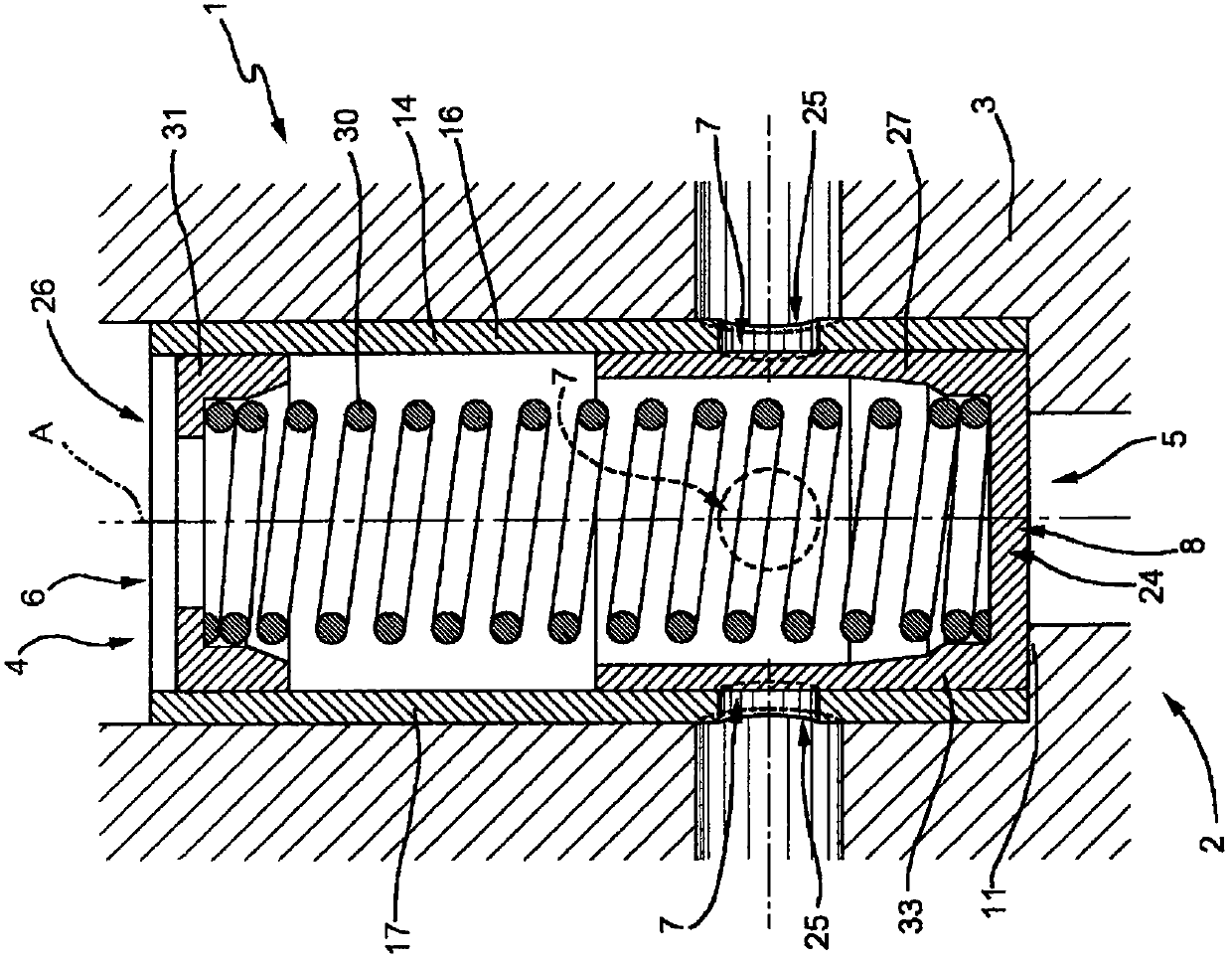
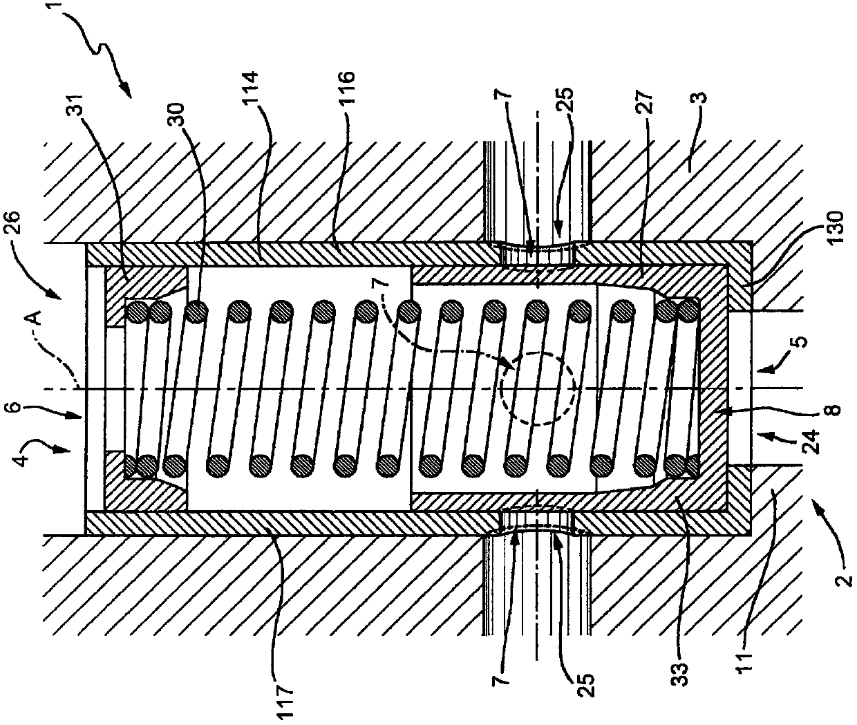
[0040] refer to figure 1 , 1 denotes the entire system for supplying fuel, preferably diesel fuel, from a reservoir (not shown) to an internal combustion engine (not shown).

[0041] The system 1 comprises: a high pressure pump 2 (only partially visible) having a pump body 3 and a seat 4 formed in the pump body 3 ; an inlet duct 5 ; a lubrication duct 6 ; a discharge duct 7 and an overflow valve 8 . An inlet duct 5 , a lubricating duct 6 and a discharge duct 7 are formed in the pump body 3 . Furthermore, the pump body 3 comprises an annular wall 11 protruding at one end of the seat 4 .

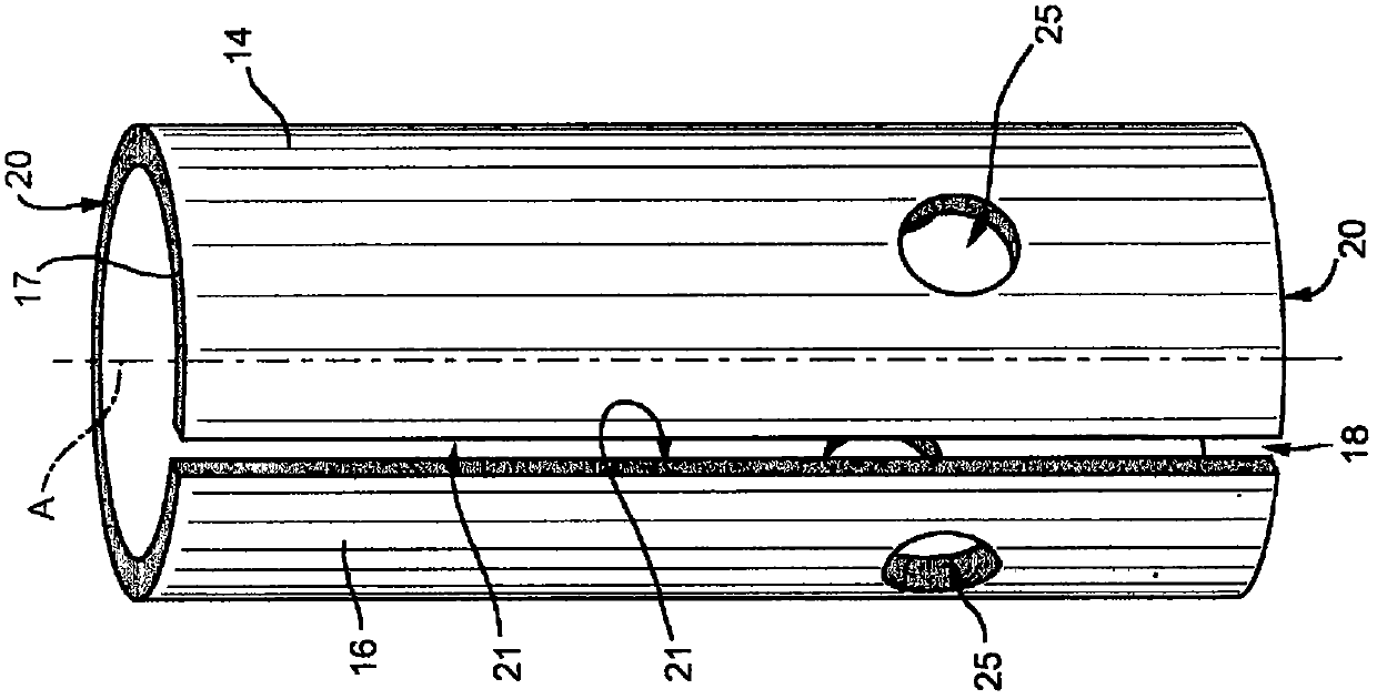
[0042] refer to figure 1 and figure 2 The overflow valve 8 comprises a valve body 14 formed by a metal plate 16 bent at least partially in the form of a cylindrical wall 17 . In more detail, the valve body 14 is a cylinder with a slot 18 along the generatrix of said cylinder. The slot 18 extends along the entire length of the cylinder. In fact, the unfolded metal sheet 16 comprises two ...


PUM


Abstract

An overflow valve (8) for a fuel feed system (1) comprising a high-pressure pump (2) having a pump body (3); the overflow valve (8) comprising a valve body (14; 114) formed by a metal sheet (16; 116) folded so as to assume at least partly the form of a cylindrical wall (17) and configured to be housed inside a seat (4) formed in the pump body (3); an inlet opening (24); a discharge opening (25); a lubrication opening (26) and a sliding member (27) movable along an axis (A) of the valve body (14; 114) so as to adjust the flow of the fuel from the inlet opening (24) to the discharge opening (25).

Description

technical field [0001] The invention relates to an overflow valve for a fuel supply system and to a method for producing such a valve. Background technique [0002] In particular, a system for supplying fuel from a reservoir to an internal combustion engine includes a high-pressure pump having a pump body and a seat formed in the pump body; the overflow valve includes: a valve body accommodated in the seat formed in the pump body , an inlet, a discharge, a lubrication port and a closure element movable along the axis of the valve body to regulate fuel flow from the inlet to the discharge. [0003] The valve body is formed by means of turning and / or drilling and / or grinding of a solid blank metal cylinder and is screwed into the pump body. [0004] A disadvantage of the prior art is that the valves produced thereby are expensive and require long processing times. In fact, during machining, 60% of the material of the solid cylinder is removed, resulting in wasted material. ...

Claims


Application Information

Patent Timeline
Patent Type & Authority Patents(China)
IPC IPC(8): F02M37/00F04B53/10F04B53/22F16K17/04
Inventor B·洛亚科诺L·梅代亚E·德马特斯
Owner ROBERT BOSCH GMBH
Why Eureka
Try Eureka