


Quick Research
Generate reliable direction feasibility study reports for your R&D in just a few steps.

Technical Q&A
Discover and master advanced knowledge NOW. Basics, ideas, possibilities, all at once.

Find Solutions
As an expert in R&D theories, this can generate solutions to your technical problems instantly.

Evaluate Feasibility
Analyze your overall solution with one click, know your potential R&D risks in advance.

Monitor Landscape
Get weekly tech updates, stay abreast of the latest tech innovations and key insights.
Mould comprising mobile elements which are obtained by sintering
A technology for molds and molding components, applied in the field of movable components, can solve problems such as complex assembly, and achieve the effect of promoting demoulding and easy demoulding
- Summary
- Abstract
- Description
- Claims
- Application Information
AI Technical Summary
Problems solved by technology
Method used
Image

Examples
Embodiment Construction
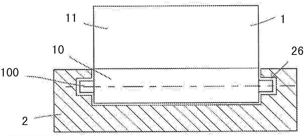
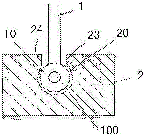
[0036] figure 1 and figure 2 The example shown in shows a liner comprising an articulated molded element 1 and a liner body 2 through which a cylindrical hole 20 passes. The molding element 1 comprises a molding part 11 , which in this case is a rectilinear part starting from the cylindrical part 10 , and a cylindrical part 10 arranged in a cylindrical hole 20 . The cylindrical part 10 rotates around the axis X and has on each side a cylindrical spigot 100 acting as a hinge, each cooperating with an orifice 26 extending the cylindrical hole 20 .
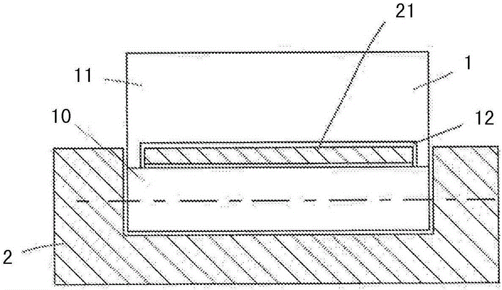
[0037] image 3 and Figure 4 The example shown in FIG. 1 shows a hinged molded element in which the molded part 11 has a notch 12 in which the peripheral part 21 of the liner body 2 can slide.
[0038] exist Figure 5 In the example shown, the molding element 1 has a cylindrical portion 10 pierced with a hole 101 into which a rod 22 with axis X is inserted and fixed to the inner liner 2 .
[0039] exist Image 6, the linear...
PUM
| Property | Measurement | Unit |
|---|---|---|
| thickness | aaaaa | aaaaa |
Abstract
Description
Claims
Application Information
 - R&D Engineer
- R&D Manager
- IP Professional
- Industry Leading Data Capabilities
- Powerful AI technology
- Patent DNA Extraction
Browse by: Latest US Patents, China's latest patents, Technical Efficacy Thesaurus, Application Domain, Technology Topic, Popular Technical Reports.
© 2024 PatSnap. All rights reserved.Legal|Privacy policy|Modern Slavery Act Transparency Statement|Sitemap|About US| Contact US: help@patsnap.com