Multispectral reflection type collimator

A collimator and reflective technology, applied in the field of multi-spectral reflective collimator, can solve the problems of large weight of aspheric mirror, low detection accuracy, high processing requirements of aspheric mirror, etc., to ensure achromatism and output light Consistent effect of parallelism

Pending Publication Date: 2017-05-10
上海镭昊光电股份有限公司
View PDF2 Cites 9 Cited by
  • Summary
  • Abstract
  • Description
  • Claims
  • Application Information

AI Technical Summary

Problems solved by technology

Although this method reduces the volume of the collimator to a certain extent, the focal length is also reduced, resulting in low detection accuracy, and because the infrared lens is used, there is chromatic aberration, which can only meet the test of a narrow spectral range need
As another example, the Chinese invention patent CN201903683U proposes that an infrared target micro-collimator is constructed by using an optical path structure of an aspheric reflector and a plane reflector. This method reduces the volume of the collimator under the premise of the same focal length , but because only one aspheric mirror is used, in order to ensure the image quality, the processing requirements for the aspheric mirror are very high, and the cost is high. Moreover, due to the largest use of optical glass materials, the weight of the aspheric mirror is heavy

Method used


Image

  • Multispectral reflection type collimator
  • Multispectral reflection type collimator
  • Multispectral reflection type collimator

Examples


Embodiment Construction

[0019] The present invention will now be further described in detail in conjunction with the accompanying drawings. The accompanying drawings are simplified schematic diagrams, which only schematically illustrate the basic structure of the present invention, and therefore only show the configurations related to the present invention.

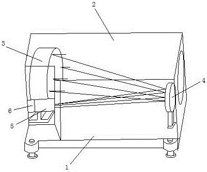
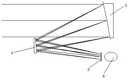
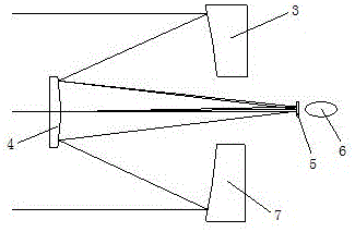
[0020] Such as figure 1 , figure 2 As shown, embodiment one, a multi-spectral reflective collimator, includes a base 1, a housing 2 installed on the base 1, the housing 2 is provided with a lens group and a power supply; the lens group It is a reflective lens group structure, the reflective lens group structure includes a first primary mirror 3 and a secondary mirror 4, the horizontal positions of the first primary mirror 3 and the secondary mirror 4 are opposite, and the height positions are staggered up and down; the A target 5 and a light source 6 are arranged on the side of the housing 2 , and the light source 6 is arranged on the focal pl...


PUM

PropertyMeasurementUnit
Effective focal lengthaaaaaaaaaa

Abstract

The invention belongs to the optical equipment technology field, to be specific, relates to a multispectral reflection type collimator. The multispectral reflection type collimator comprises a base; a housing disposed on the base; a lens group and a power supply, which are disposed in the housing. The lens group adopts a reflection type lens group structure, which comprises a first primary lens and a secondary lens. The horizontal position of the first primary lens and the horizontal position of the secondary lens are opposite to each other, and the height position of the first primary lens and the height position of the secondary lens are in an up-down staggered arrangement. The side surface of the housing is provided with a target and a light source, and the focal plane of the target is provided with the light source. By adopting the above mentioned structure, a Zemax optical design software is adopted, and the reflection type structure is adopted, and then achromatism under a condition of different spectrums is guaranteed, and the output light parallelism of different spectrums is consistent; difficulty in simultaneous detection of different wavelength spectrums is solved, and at the same time a testing standard is provided for the coaxial system of the multispectral optical system. The multispectral reflection type collimator is widely used for the optical performance testing of various products, and foundation is laid for guarantee of infrared imaging product quality.

Description

technical field [0001] The invention belongs to the technical field of optical equipment, and in particular relates to a multi-spectral reflective collimator. Background technique [0002] At present, in order to meet different applications under multiple spectral wavelength conditions, including visible light, infrared light, and the common application of various laser wavelengths, a multi-spectral parallel light device is required for image simulation and various optical properties. detection. [0003] For example, Chinese invention patent CN200910060891.9 provides a method for a small collimator. The technical approach is to place an infrared lens in a metal sleeve and place a hollow metal target on the focal plane of the infrared lens to achieve distant targets. simulation. Although this method reduces the volume of the collimator to a certain extent, the focal length is also reduced, resulting in low detection accuracy, and because the infrared lens is used, there is ...

Claims


Application Information

Patent Timeline
IPC IPC(8): G01M11/02G02B27/00
CPCG02B27/00G01M11/02
Inventor 郑斐钟朱沛林庄向阳傅进生
Owner 上海镭昊光电股份有限公司
Why Eureka
Try Eureka