
A dual-mode launching device for airborne missiles

A technology for launchers and airborne missiles, which is applied in the direction of launchers, etc., can solve the problems of the influence of fighters' comprehensive combat effectiveness and the difficulty of further improving the loading efficiency, so as to improve the loading efficiency and fighters' comprehensive combat effectiveness and shorten the loading time Effect

Inactive Publication Date: 2018-01-16
SHENYANG AEROSPACE UNIVERSITY
View PDF7 Cites 0 Cited by
  • Summary
  • Abstract
  • Description
  • Claims
  • Application Information

AI Technical Summary

Problems solved by technology

[0005] Although both the rail-type launch method and the ejection-type launch method have their own characteristics and advantages, the launch devices corresponding to both are single-mode, that is, the rail-type launch device can only be adapted to missiles that use rail-type launches, while the ejection The type launcher can only be adapted to missiles launched by catapult. When the missile model of a certain mounting point needs to be replaced, the corresponding launcher needs to be replaced, which makes it difficult to further improve the loading efficiency. Comprehensive combat effectiveness will also be affected

Method used


Image

  • A dual-mode launching device for airborne missiles
  • A dual-mode launching device for airborne missiles
  • A dual-mode launching device for airborne missiles

Examples


Embodiment Construction

[0023] The present invention will be further described in detail below in conjunction with the accompanying drawings and specific embodiments.

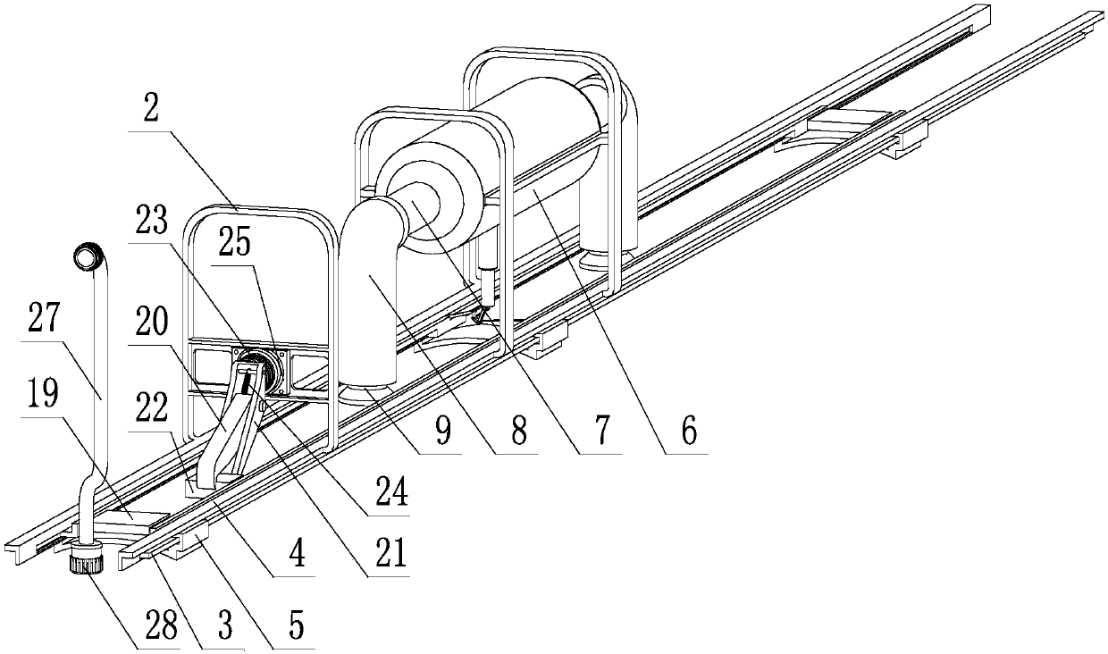
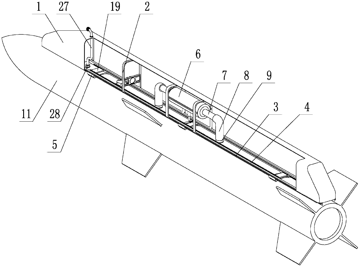
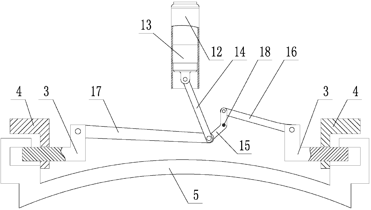
[0024] like Figure 1~5 As shown, an airborne missile dual-mode launching device includes a shell 1, a rib 2, a guide rail 3, a guide rail fixing frame 4, a slider 5, a bomb combustion chamber 6, a missile body ejection air duct 7, and a missile body Ejection piston barrel 8, projectile ejection push rod 9 and guide rail slider separation drive mechanism;

[0025] The housing 1 is fixedly connected to the missile carrier, the number of the ribs 2 is several, and the ribs 2 are fixed on the inner side of the housing 1, and the guide rail holder 4 is provided with two, and the two guide rail holders 4 are parallel to each other. Set; two described guide rail fixing frames 4 are fixedly connected on the ribs 2, on the two guide rail fixing frames 4, there are guide rail fixing ports 10, and in the guide rail fixing ports 10 of the two g...


PUM


Abstract

The invention discloses a dual-mode launcher for an airborne missile. A shell is fixedly connected to a missile carrier, a plurality of ribs are fixedly installed inside the shell, two guide rail fixing racks arranged in parallel are fixedly connected to the ribs, each guide rail fixing rack is provided with a guide rail fixing port, two guide rails are respectively located inside the guide rail fixing ports of the guide rail fixing racks, a slide block is hung on the two guide rails, and the lower end of the slide block is fixedly connected with a missile body; a cartridge combustion chamber is fixedly arranged on the ribs, high-pressure jet ports at two ends of the cartridge combustion chamber are respectively connected with a missile ejection gas-guide tube, a missile ejection piston barrel is arranged vertical to the missile body, the upper opening of the missile ejection piston barrel is communicated with the missile ejection gas-guide tube, a missile ejection push rod is located inside a missile ejection piston barrel body, the missile ejection push rod has axial telescopic degree of freedom relative to the missile ejection piston barrel, and a guide rail and slide block separation driving mechanism is connected between each guide rail and the cartridge combustion chamber; a buffer is installed between the two guide rails; and a latching mechanism is installed between the ribs and the missile body.

Description

technical field [0001] The invention belongs to the technical field of airborne missile launching, in particular to a dual-mode launching device for airborne missiles. Background technique [0002] For modern warfare, capturing air supremacy has become a key factor in determining the direction of the war. In order to seize air supremacy, fighter planes need to mount a large number of missiles, and the mounting points of missiles can be located under the fuselage, under the wings, at the tip of the wings or in the belly of the aircraft. According to different types of missiles, the launch methods of missiles are also divided into rail launch and catapult launch. [0003] Guide-rail launch is also called self-propulsion launch. The missile relies on its own engine or booster to provide thrust to make the missile break away from the guide rail of the launcher. During the gliding process before the missile leaves the launching device, it will be constrained and guided by the gu...

Claims


Application Information

Patent Timeline
Patent Type & Authority Patents(China)
IPC IPC(8): F41F7/00
CPCF41F7/00
Inventor 祁武超李东伟刘恒
Owner SHENYANG AEROSPACE UNIVERSITY
Learn More