
Eccentric vibration device of road roller and arranging structure thereof

A technology of vibrating device and arranging structure, applied in the field of vibration of road rollers, can solve the problems of difficult adjustment, different tolerance, difficult installation, etc., and achieve the effect of reducing the difficulty of manufacturing and installation, high stability and reliability, and not easy to damage

Pending Publication Date: 2017-05-10
合肥永安绿地工程机械有限公司
View PDF9 Cites 6 Cited by
  • Summary
  • Abstract
  • Description
  • Claims
  • Application Information

AI Technical Summary

Problems solved by technology

[0002] At present, the vibration amplitude of vibratory rollers on the market is mostly fixed and cannot be adjusted. In the actual construction process, for different subgrade road sections, their tolerance to tamping is different. The impact force is too small, and it is not easy to stabilize the roadbed, so the vibratory roller needs to apply different amplitudes according to specific situations
In recent years, although there have been movable eccentric blocks that can adjust the amplitude of vibratory rollers, the structure of the existing movable eccentric blocks is relatively complicated, which is not only difficult to install, but also difficult to adjust. At the same time, the complex structure of movable eccentric blocks is easy to be damaged during vibration.
Obviously, the eccentric vibrating mechanism of the existing vibratory roller cannot meet the actual needs and needs to be improved urgently

Method used


Image

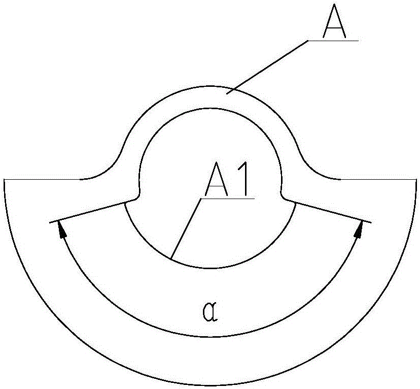
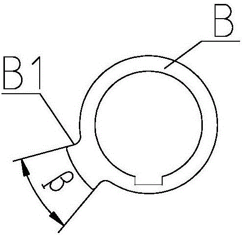
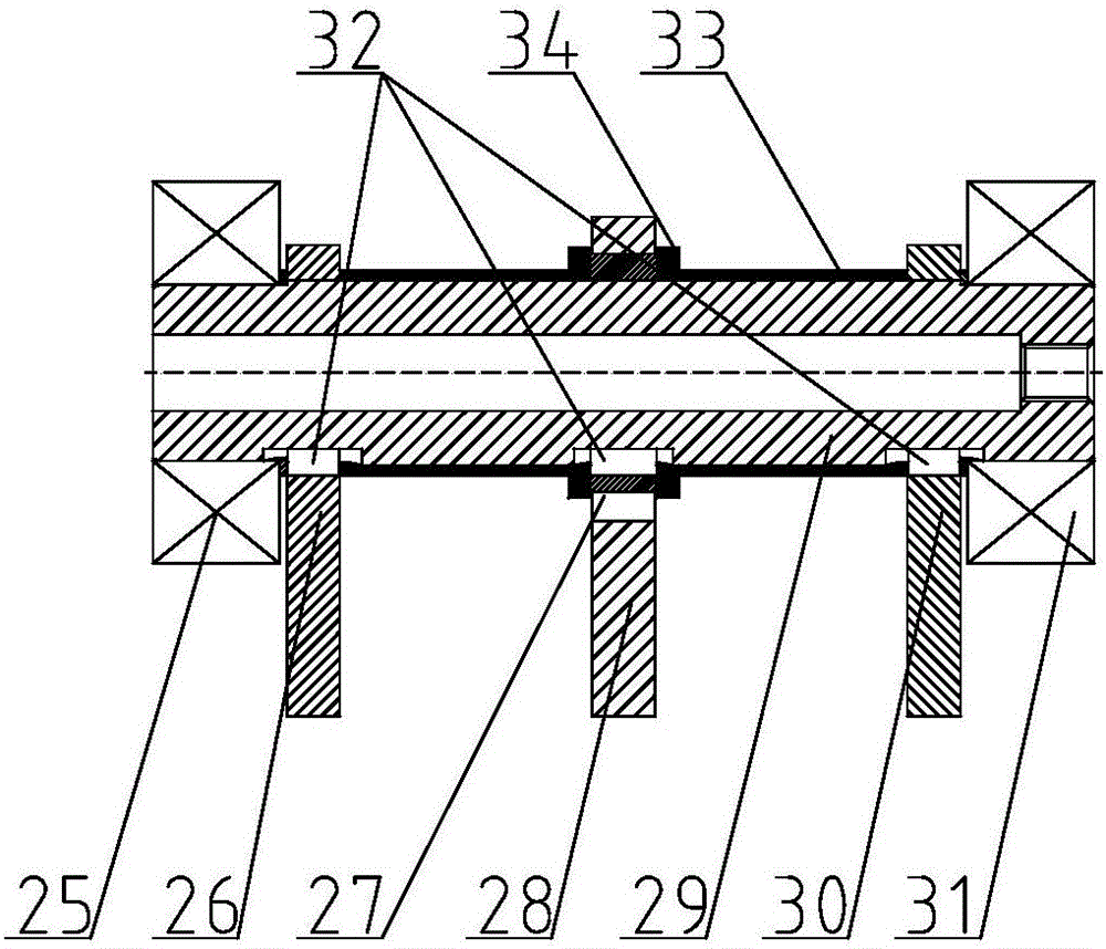
  • Eccentric vibration device of road roller and arranging structure thereof
  • Eccentric vibration device of road roller and arranging structure thereof
  • Eccentric vibration device of road roller and arranging structure thereof

Examples


Embodiment 1

[0086] Embodiment 1, only the movable eccentric mass group is set on the vibration axis

[0087] If the fixed eccentric block group is not provided on the vibration shaft, but only the movable eccentric block group is provided, the position of the movable eccentric block group on the same vibration shaft has the following setting methods:

[0088] In the first arrangement mode, the movable eccentric mass group is symmetrically arranged on both sides of the vibration axis along the center of the vibration axis;

[0089] The second setting method, wherein one set of movable eccentric mass groups is arranged in the middle of the vibration axis, and all other movable eccentric mass groups are symmetrically arranged on both sides of the vibration axis along the center of the vibration axis;

[0090] You can choose one of the above two setting methods during installation.

Embodiment 2

[0091] Embodiment 2, the fixed eccentric block and the movable eccentric block are set on the same vibration axis at the same time

[0092] The device also includes a fixed eccentric mass set arranged on the vibrating shaft, the fixed eccentric mass set and the movable eccentric mass set are independently arranged; the fixed eccentric mass set and the movable eccentric mass set cooperate with each other so that when When the vibration axis rotates forward or reversely, the vibrations of the fixed eccentric mass set and the movable eccentric mass set are superimposed or canceled each other.

[0093] The positions of the fixed eccentric block group and the movable eccentric block group on the same vibration axis are set as follows:

[0094] In the first setting mode, the fixed eccentric mass group is symmetrically arranged on both sides of the vibration axis along the center of the vibration axis, and the movable eccentric mass group is also symmetrically arranged on both sides ...

Embodiment 3

[0110] Embodiment 3, set movable eccentric block group and / or fixed eccentric block on different vibration axes

[0111] Embodiment 3.1 The vibration shaft is set to two, and the two vibration shafts are arranged symmetrically along the central axis of the exciter housing; The eccentric moments of the eccentric mass groups on the vibrating shaft are equal to each other. The positions of the eccentric block groups on the two vibration axes are set as follows:

[0112] In the first setting mode, the two vibrating shafts are equipped with movable eccentric block groups and only;

[0113] In the second setting method, one vibration shaft is provided with a movable eccentric block group, and the other vibration shaft is provided with a fixed eccentric block group;

[0114] In the third setting mode, a movable eccentric block group and a fixed eccentric block group are arranged on one vibrating shaft, and a movable eccentric block group is arranged on the other vibrating shaft;

...


PUM


Abstract

The invention relates to an eccentric vibration device of a road roller and an arranging structure thereof. The device comprises a vibration shaft and a movable eccentric block group, wherein the movable eccentric block group is arranged on the vibration shaft; the movable eccentric block group comprises movable eccentric blocks, limiting rings and fixing keys; the limiting rings are fixed to the vibration shaft through the fixing keys, limiting grooves being matched with limiting convex blocks on the limiting rings are formed in the movable eccentric blocks, and the central angles of the limiting grooves are equal to or larger than those of the limiting convex blocks; and when the central angles of the limiting grooves are larger than those of the limiting convex blocks, the limiting grooves are matched with the limiting convex blocks, so that when the vibration shaft positively rotates or negatively rotates, the movable eccentric blocks provided with two vibration limitation positions correspondingly. According to the eccentric vibration device of the road roller and the arranging structure thereof, structures of the movable eccentric blocks are greatly simplified, and manufacturing and installing difficulties of the eccentric blocks are lowered; and meanwhile, the movable eccentric blocks are integrally formed, thus the movable eccentric blocks are not prone to being damaged during using, and during working, stability and reliability are highly maintained.

Description

technical field [0001] The invention belongs to the technical field of road roller vibration, and in particular relates to an eccentric vibration device of a road roller and an arrangement structure thereof. Background technique [0002] At present, the vibration amplitude of vibratory rollers on the market is mostly fixed and cannot be adjusted. In the actual construction process, for different subgrade road sections, their tolerance to tamping is different. The impact force is too small, and it is not easy to stabilize the roadbed, so the vibratory roller needs to apply different amplitudes according to specific situations. In recent years, although movable eccentric blocks that can adjust the amplitude of vibratory rollers have appeared, the structures of existing movable eccentric blocks are relatively complicated, which are not only difficult to install, but also difficult to adjust. At the same time, complex structures of movable eccentric blocks are easily damaged dur...

Claims


Application Information

Patent Timeline
Patent Type & Authority Applications(China)
IPC IPC(8): E01C19/28
CPCE01C19/286
Inventor 黄方权宋皓崔文平
Owner 合肥永安绿地工程机械有限公司
Learn More