
A cable retractable device for electric power test

A retractable device and power test technology, which is applied in the field of cable retraction, can solve the problems of reduced cable service life, excessive bending angle, cable damage, etc., and achieve the effect of improving quality and efficiency and improving structure

Active Publication Date: 2018-09-04
安徽亿力电力设备有限公司
View PDF8 Cites 0 Cited by
  • Summary
  • Abstract
  • Description
  • Claims
  • Application Information

AI Technical Summary

Problems solved by technology

[0002] In the power test, a large number of cables are required for testing. Since there are many brittle wires inside the cables, if they are randomly placed during collection, the bending angle is too large, which will easily lead to cable damage. Reduce the service life of the cable, so the cable needs to be retracted reasonably to avoid this problem
[0003] There are many cable retracting devices on the market, including simple and complex, manual and fully automatic, but these cable retracting devices still have certain deficiencies in structure, such as the fixing of the initial thread end, which often requires Stick it with tape, and then when the machine is started, manually assist the rotation for one to two turns to complete the winding work. At the same time, when the winding is completed, the wound coil needs to be bundled and collected before the next winding, binding and The winding cannot be carried out at the same time, resulting in a great reduction in the efficiency of the winding work

Method used


Image

  • A cable retractable device for electric power test
  • A cable retractable device for electric power test
  • A cable retractable device for electric power test

Examples


Embodiment Construction

[0023] The following will clearly and completely describe the technical solutions in the embodiments of the present invention with reference to the accompanying drawings in the embodiments of the present invention. Obviously, the described embodiments are only some, not all, embodiments of the present invention. Based on the embodiments of the present invention, all other embodiments obtained by persons of ordinary skill in the art without making creative efforts belong to the protection scope of the present invention.

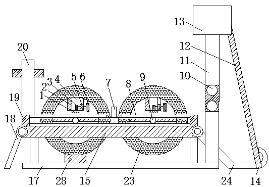
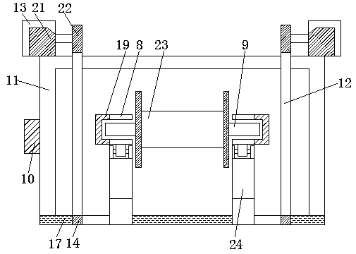
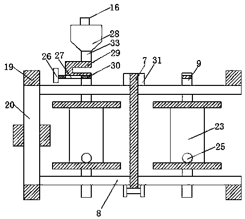
[0024] see Figure 1-7 , the present invention provides a technical solution: a cable retractable device for electric power testing, including a base 17, the upper surface of the base 17 is fixedly connected to the support plate 15 through a fixed bracket, the upper surface of the support plate 15 is welded with a chute 8, the chute The outer two ends of 8 are all welded with fixed groove 19, and one end of support plate 15 is connected with first rotating pla...


PUM


Abstract

The invention discloses a cable taking-up and paying-off device for power tests. The cable taking-up and paying-off device for power tests comprises a base. A supporting plate is fixedly connected to the upper surface of the base through a fixing support. A sliding chute is welded to the upper surface of the supporting plate. Fixed chutes are welded to the two ends of the outer side of the sliding chute. One end of the supporting plate is connected with a first rotating plate through a shaft. The other end of the supporting plate is connected with a second rotating plate through a shaft. A fixing buckle is welded to the outer side of the second rotating plate through a support. A framework is welded to one end of the upper surface of the base. A motor switch is fixedly connected to one side face of the framework. Motor cases are fixedly connected to the two ends of the upper surface of the framework. Motors are fixedly connected to the interiors of the motor cases. The cable taking-up and paying-off device for power tests is perfect relatively in structure, the start end of a cable can be effectively fixed during taking-up of the cable, the binding and winding operations can be carried out simultaneously, and quality and efficiency of the cable taking-up work are improved.

Description

technical field [0001] The invention relates to the technical field of cable retraction, in particular to a cable retraction device for electric power testing. Background technique [0002] In the power test, a large number of cables are required for testing. Since there are many brittle wires inside the cables, if they are randomly placed during collection, the bending angle is too large, which will easily lead to cable damage. The service life of the cable is reduced, so the cable needs to be retracted reasonably to avoid this problem. [0003] There are many cable retracting devices on the market, including simple and complex, manual and fully automatic, but these cable retracting devices still have certain deficiencies in structure, such as the fixing of the initial thread end, which often requires Stick it with tape, and then when the machine is started, manually assist the rotation for one to two turns to complete the winding work. At the same time, when the winding i...

Claims


Application Information

Patent Timeline
Patent Type & Authority Patents(China)
IPC IPC(8): B65H75/44
CPCB65H75/4486B65H2701/34
Inventor 孙剑波方振伟季翠娜孙韬张文斌张军苗王德刚荆咏梅
Owner 安徽亿力电力设备有限公司
Learn More