Illumination unmanned aerial vehicle

A drone and main body technology, applied in the field of drones, can solve the problem that the lighting angle cannot be adjusted, and achieve the effect of increasing clarity

Active Publication Date: 2017-05-10
NANTONG ZHONGTIE HUAYU ELECTRICS
View PDF7 Cites 5 Cited by
  • Summary
  • Abstract
  • Description
  • Claims
  • Application Information

AI Technical Summary

Problems solved by technology

However, the position of the lighting of the aerial lighting UAV is fixed, and the lighting angle cannot be adjusted.

Method used


Image

  • Illumination unmanned aerial vehicle
  • Illumination unmanned aerial vehicle
  • Illumination unmanned aerial vehicle

Examples


Embodiment

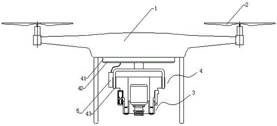
[0027]This embodiment illuminates the drone, such as image 3 As shown, it includes a UAV body 1, a rotor 2, a cloud platform and an integrated camera and lighting assembly 3, and the rotor 2 is installed on the UAV body 1 and is located at the top of the UAV body 1; 4, and the pan-tilt controller 5 that is arranged on the pan-tilt bracket 4, the pan-tilt bracket 4 includes a fixed frame 41, a shaft frame 42 and a load bearing part 43; The fixed frame 41 is connected to the load supporting part 43, and the integrated imaging and lighting assembly 3 is supported in the loading supporting part 43, and the integrated imaging and lighting assembly 3 is located at the lower end of the platform.

[0028] Such as Figure 4 As shown, the camera and lighting integrated assembly 4 includes a base 41 , a lens cover 42 , an adjustment seat 43 and a camera assembly 44 fixedly arranged in the inner cavity of the base 41 through a bracket.

[0029] The base 41 is a stepped base shaft body,...


PUM


Abstract

The invention relates to an illumination unmanned aerial vehicle which comprises an unmanned aerial vehicle body, a rotor wing, a pan-tilt and a photographing and illumination integrated assembly. The rotor wing is installed on the unmanned aerial vehicle body and located at the top end of the unmanned aerial vehicle body. The pan-tilt is installed on the unmanned aerial vehicle body and located at the bottom end of the unmanned aerial vehicle body. The photographing and illumination integrated assembly is fixedly connected with the pan-tilt and located at the lower end of the pan-tilt. The photographing and illumination integrated assembly comprises a base, a lens cover, an adjusting base and a photographing assembly fixedly arranged in an inner cavity of the base through a support. The illumination unmanned aerial vehicle has the advantages that the pan-tilt is adopted for fixedly connecting illumination and photographing devices to the unmanned aerial vehicle body, and the angle is adjusted in an omnibearing mode; meanwhile, by additionally arranging a guiding positioning pin and a guiding chute matched with the guiding positioning pin, the photographing assembly can stretch and retract back and forth to be adjusted; in addition, a heat dissipation region is further arranged on a lens base of the lens cover, and excessive heat can be effectively avoided.

Description

technical field [0001] The invention belongs to the technical field of unmanned aerial vehicles, and in particular relates to an illuminated flying unmanned aerial vehicle. Background technique [0002] All kinds of natural disasters and emergencies occur frequently in modern society. If the progress of the situation cannot be understood in time, it will seriously limit the rescue assessment of disasters and the control and handling of emergencies, resulting in more serious casualties and economic losses. Therefore, There is an urgent need for a real-time dynamic system with wide range, strong mobility and high information synchronization. With the development of UAV technology, its applications are becoming wider and wider, and it has shown indispensable importance in both civilian and military fields, especially in the application of aerial photography. UAVs are used as aerial photography The platform has become the mainstream of current development. However, most of the...

Claims


Application Information

Patent Timeline
Patent Type & Authority Applications(China)
IPC IPC(8): B64D47/04B64D47/08G03B17/55G03B21/14G03B30/00
CPCG03B17/55G03B21/145B64D47/04B64D47/08B64U2101/30
Inventor 何小峰何秀平
Owner NANTONG ZHONGTIE HUAYU ELECTRICS
Why Eureka
Try Eureka