Integrated cleaning device for power equipment flashover prevention

A technology for power equipment and cleaning devices, applied in the direction of cleaning methods using liquids, cleaning methods and utensils, and cleaning methods using tools, etc., which can solve problems such as personal health injuries, easy to scrub dead ends, and high fatigue intensity

Inactive Publication Date: 2017-05-10
刘刚
View PDF0 Cites 0 Cited by
  • Summary
  • Abstract
  • Description
  • Claims
  • Application Information

AI Technical Summary

Problems solved by technology

Before the arrival of spring and autumn every year, rain and fog increase. In order to prevent flashover accidents caused by dirt and dust on power equipment, the porcelain parts (mainly insulators) of power equipment need to be dust-removed and cleaned, and then painted. Anti-fouling flash paint, this work requires a lot of manual work, and the staff wipes it bit by bit with a rag in their hands. The workload is very heavy and the intensity of fatigue is very high.
Moreover, it is inconvenient for the staff to stand and move when cleaning on the equipment, so they can only work with one hand, and the other hand must hold the porcelain column to ensure personal safety and prevent falling from high altitudes. If you can touch the equipment at close range, you will inhale a large amount of dust at the same time, which will also cause considerable damage to your health.
[0003] At present, there is a device on the market that uses the extension rod to lift the rag into the air to scrub the power system equipment, which can solve the problem of dust inhalation or contamination due to the traditional scrubbing method being too close to the power system equipment, and has a better protective effect. , to ensure the health of the operator, but this scrubbing equipment also has the following disadvantages: 1, because the rag is lifted into the air by the extension rod for scrubbing, the scrubbing strength of the rag is greatly reduced, resulting in unclean scrubbing; 2. 1. The operation method of u...

Method used


Image

  • Integrated cleaning device for power equipment flashover prevention
  • Integrated cleaning device for power equipment flashover prevention
  • Integrated cleaning device for power equipment flashover prevention

Examples


Embodiment Construction

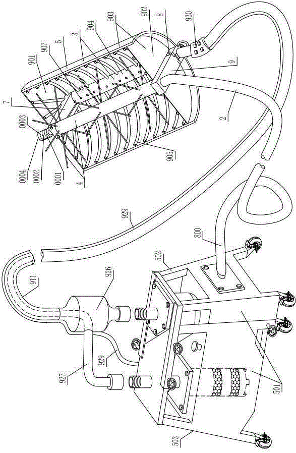
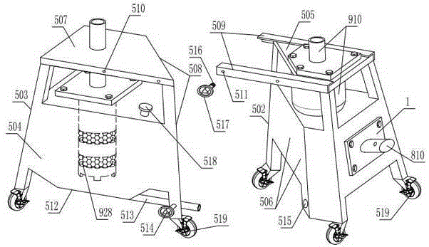
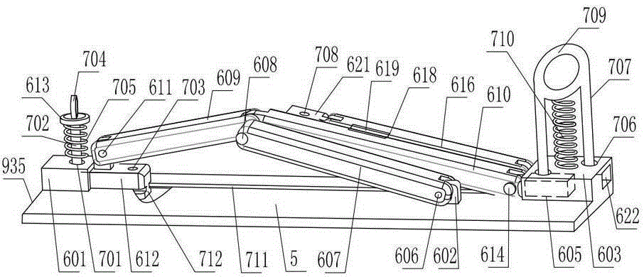
[0028] As shown in the figure, the integrated power equipment anti-flashover cleaning device includes a cleaning head 3 driven by a power unit 1 through a transmission hose 2. The cleaning head includes a vertically arranged rotating brush 4, and one side of the rotating brush is covered. There is a protective cover 5 with a C-shaped cross section, a handle 6 is fixed on the outside of the protective cover, and a horizontally extending upper rod 7 is fixed on the inner upper end of the protective cover. The end of the upper rod can only be rotated with the upper end of the rotary brush through the upper connecting device. , the lower end of the protective cover inner side is hinged with the lower rod 9 that can swing up and down through the horizontal shaft 8, the lower rod is rotated and matched with the lower end of the rotating brush through the lower connecting device, and the lower rod is also inserted and matched with the lower end of the rotating brush through the lower c...


PUM


Abstract

The invention discloses an integrated cleaning device for power equipment flashover prevention. The integrated cleaning device for power equipment flashover prevention comprises a cleaning head which is driven by a power device via a drive hose. The cleaning head comprises a vertically arranged rotary brush. One side of the rotary brush is covered with a protective cover with the C-shaped cross section. A handle is fixedly arranged on the outer side of the protective cover. A transversely extending upper rod is fixedly arranged at the upper end of the inner side of the protective cover. The end of the upper rod is in rotary fit with the upper end of the rotary brush through an upper connection device. A lower rod capable of swinging up and down is hinged to the lower end of the inner side of the protective cover through a horizontal shaft. The lower rod is in rotary fit with the lower end of the rotary brush through a lower connection device. The integrated cleaning device for power equipment flashover prevention has the advantages that the structure is reasonable, the scrubbing task can be completed quickly according to the shapes of devices to be scrubbed, the close scrubbing mode and the remote scrubbing mode can be switched freely and quickly without position shift of operators, the scrubbing angle can be adjusted at will, stubborn stains can be removed, no dead corner of scrubbing exists, and both time and labor are saved; scrubbing workers are well protected and do not inhale or be infected with dust, the situation that dirt gets in eyes is avoided, and the dust dirt removed through scrubbing cannot fall onto devices below; and the integrated cleaning device is not limited by the scrubbing height, the scrubbing task can be completed by one person independently, and the scrubbing effect is good.

Description

technical field [0001] The invention relates to an integrated anti-flashover cleaning device for electric equipment. Background technique [0002] At present, cleaning and decontamination of power equipment in the power system is a very heavy and repetitive work, and it also has certain harm to the health of the staff. Before the arrival of spring and autumn every year, rain and fog increase. In order to prevent flashover accidents caused by dirt and dust on power equipment, the porcelain parts (mainly insulators) of power equipment need to be dust-removed and cleaned, and then painted. Anti-fouling flashover coating, this work requires a lot of manual work, and the staff wipes it bit by bit with a rag in their hands. The workload is very heavy and the intensity of fatigue is very high. Moreover, it is inconvenient for the staff to stand and move when cleaning on the equipment, so they can only work with one hand, and the other hand must hold the porcelain column to ensure ...

Claims


Application Information

Patent Timeline
IPC IPC(8): B08B1/04B08B3/02B08B15/04B08B1/00B08B13/00
CPCB08B1/04B08B1/002B08B1/006B08B3/02B08B13/00B08B15/04
Inventor 刘刚
Owner 刘刚
Why Eureka
Try Eureka