
Automatic chamfering and cutting device

A cutting equipment and automatic technology, applied in the direction of stone processing equipment, work accessories, manufacturing tools, etc., can solve the problems of increasing enterprise costs, insufficient chamfering, and high costs, reducing labor costs, improving production efficiency, and reducing enterprise costs. Effect

Pending Publication Date: 2017-05-03
山东诺玛建材有限公司
View PDF7 Cites 1 Cited by
  • Summary
  • Abstract
  • Description
  • Claims
  • Application Information

AI Technical Summary

Problems solved by technology

Existing equipment for chamfering and cutting has the following significant disadvantages: 1. Unsafe
The grinding wheel is easy to break when the manual angle grinder is operated, which may easily cause injury to the operator and other personnel
2. Low efficiency
Manual angle grinders need two people to operate, the efficiency is too low, and at the same time, the labor cost is high
3. High cost
The grinding wheel used in the manual angle grinder wears quickly and needs to be replaced continuously, which increases the cost of the enterprise
4. Irregular
The product chamfered by the manual angle grinder is not in place and irregular, and the product is not beautiful

Method used


Image

  • Automatic chamfering and cutting device

Examples


Embodiment Construction

[0018] The present invention will be further described below in conjunction with the accompanying drawings and examples, and the contents of the examples are not intended to limit the protection scope of the present invention.

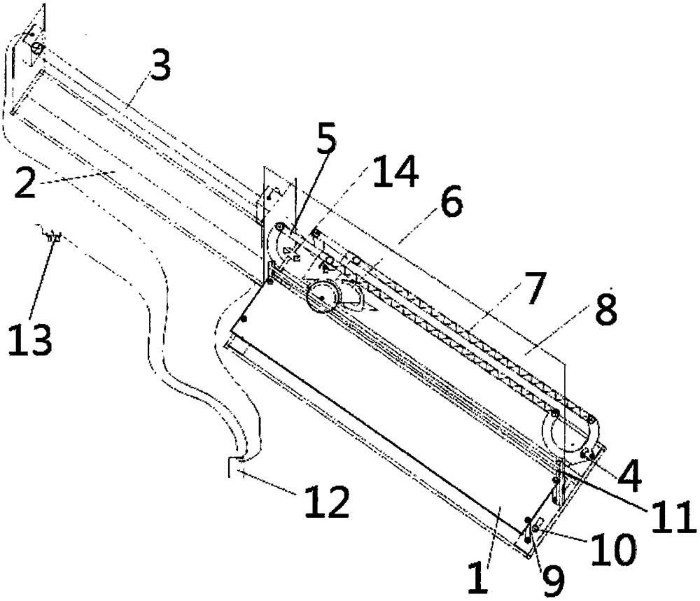
[0019] figure 1 A schematic structural view of the automatic chamfering and cutting equipment of the present invention is shown. Such as figure 1 As shown, the automatic chamfering and cutting equipment of the present invention includes an operating platform 1 . When wall tiles are cut or chamfered, the wall tiles are placed on the operating platform 1 . In the present invention, preferably, the operating platform 1 is provided with a height adjusting screw 9 and a front and rear adjusting screw 10 . Wherein, the height of the operating platform 1 can be adjusted through the height adjusting screw 9 . The operating platform 1 can be adjusted forward and backward by the forward and backward adjusting screw 10 . In this way, the adjustment of the op...


PUM


Abstract

The invention relates to an automatic chamfering and cutting device. The automatic chamfering and cutting device comprises an operation platform (1). An angle adjusting plate (4) is arranged at each of the two ends of the operation platform (1). Two tracks (5) are arranged between the two angle adjusting plates (4). The tracks (5) are provided with an electric cutting machine (6). A telescopic dustproof cover (7) is arranged on one side of the electric cutting machine (6), and a transparent dustproof baffle (8) is arranged on the other side of the electric cutting machine (6). An air cylinder base (2) is arranged at one end of the operation platform (1) and provided with an air cylinder (3). A cylinder rod of the air cylinder (3) is connected with the electric cutting machine (6). The automatic chamfering and cutting device further comprises a foot control valve (12) and an automatic oil feeder (13). The foot control valve (12) is connected with the air cylinder (3), the electric cutting machine (6) and the automatic oil feeder (13). One person is enough for operating the device, simpleness and convenience are achieved, the work efficiency is improved, and cost is reduced; and meanwhile, unsafe factors can be eliminated, accidental injuries of workers are eradicated, and the work environment can be improved.

Description

technical field [0001] The invention belongs to the technical field of processing equipment for decorative wall tiles, and relates to a cutting device for chamfering wall tiles, in particular to an automatic chamfering cutting device. Background technique [0002] After the existing decorative wall tiles are produced, their side parts have different regularity, which leads to joints that are prone to appear when the wall tiles are combined. Therefore, when pasting wall tiles, it is usually necessary to cut and chamfer the wall tiles. [0003] The equipment currently used for cutting the chamfering of decorative wall tiles is mainly a portable cutting machine and an angle grinder. When cutting, the two tools are equipped with different saw blades. The existing equipment for chamfering and cutting has the following significant disadvantages: 1. It is not safe. When the manual angle grinder is operated, the grinding wheel is easy to break, which may easily cause injury to th...

Claims


Application Information

Patent Timeline
IPC IPC(8): B28D1/04B28D7/02
Inventor 宋正功
Owner 山东诺玛建材有限公司
Learn More