Distribution Network Traveling Wave Fault Location Method Based on Time Analysis Matrix and Cluster Analysis
A technology of time analysis and cluster analysis, applied in the directions of fault location, fault detection by conductor type, data processing application, etc., can solve the problems of line length error, wave speed influence, abnormal terminal data and so on
- Summary
- Abstract
- Description
- Claims
- Application Information
AI Technical Summary
Problems solved by technology
Method used
Image
Examples
Embodiment 1
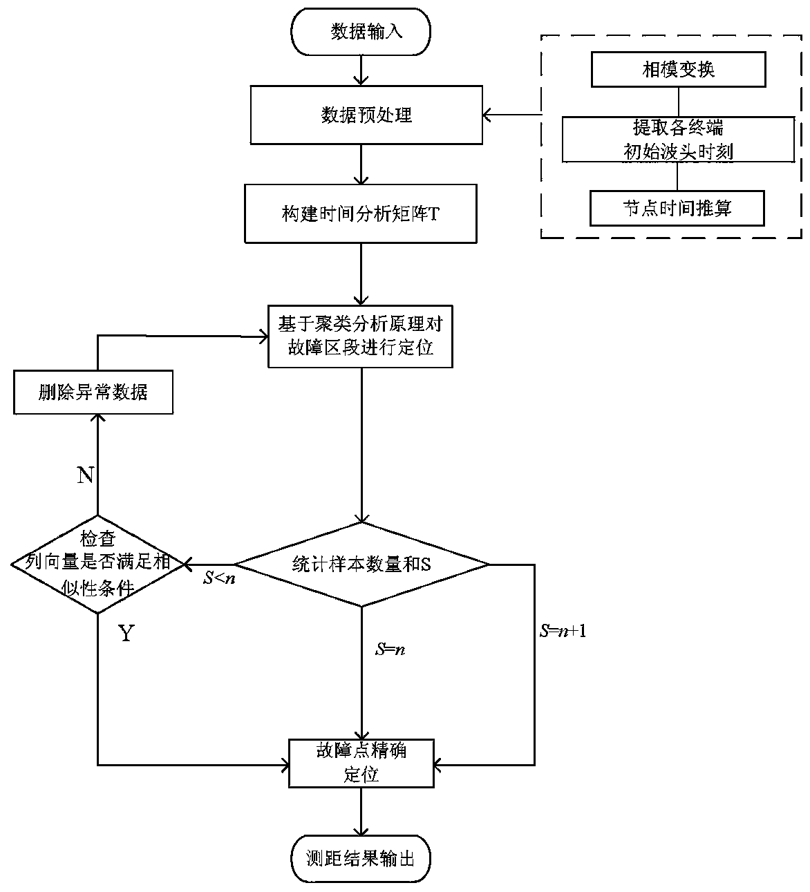
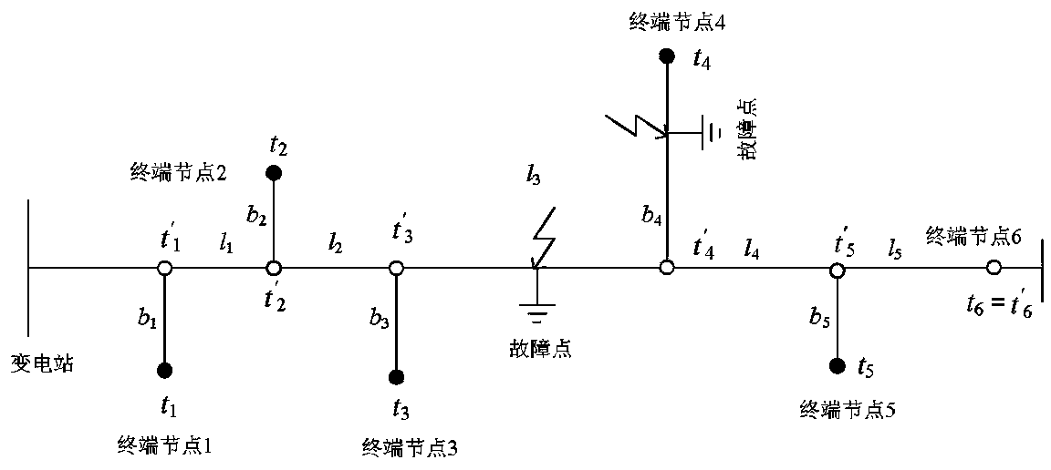
[0042] Embodiment 1: as attached figure 1 , 2 As shown, the distribution network traveling wave fault location method based on time analysis matrix and cluster analysis includes the following steps:
[0043] The first step: input data, perform data preprocessing, data preprocessing includes: 1) phase-mode transformation, using Karen Bell transformation to transform the three-phase voltage into line-mode components and zero-mode components, extracting line-mode components for analysis; 2) Find the initial moment of the fault, use the wavelet transform to detect the sudden change point of the transient signal, and use it as the initial moment when the transient traveling wave arrives at each measurement node; two steps;
[0044] Step 2: Construct a time analysis matrix, take each backbone node as the starting point of the traveling wave, calculate the initial wave head time of each node along the line segmentally, and use the initial wave head time of the nodes calculated base...
Embodiment 2
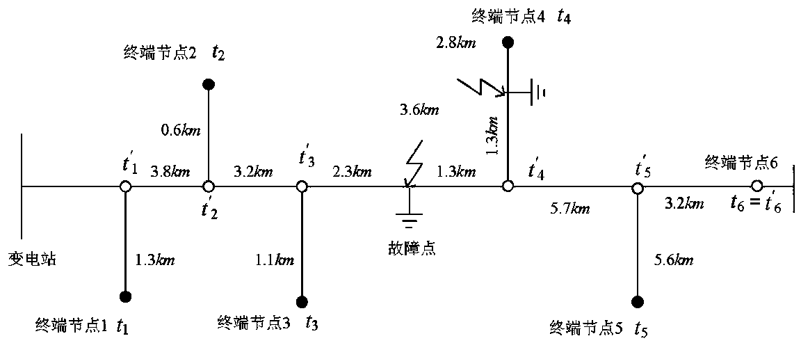
[0075] Embodiment 2: as attached figure 1 , 2 As shown in , 3, a simulation model was built using the 10kV Datong Line in Huainan, Anhui Province as a template. The main line length is 19.5km, and the length of each branch line is shown in the figure above. Positioning terminal devices are installed at the end of the line and the ends of the five main branch roads. The sampling rate is 1.25MHz with reference to the actual device. The transmission line model is built with reference to the actual line structure, using a double-circuit structure. The simulation includes two types of faults. The steps are as follows:
[0076] The fault point is about 2.3km away from node 3 on the main line, and the fault location calculation follows the steps below:
[0077] Step 1: Input data, perform data preprocessing, perform phase-mode transformation on the three-phase voltage and convert it into line-mode components and zero-mode components, extract line-mode components for analysis, and ex...
Embodiment 3
[0088] Embodiment 3: as attached figure 1 , 2 As shown in , 3, a simulation model was built using the 10kV Datong Line in Huainan, Anhui Province as a template. The main line length is 19.5km, and the length of each branch line is shown in the figure above. Positioning terminal devices are installed at the end of the line and the ends of the five main branch roads. The sampling rate is 1.25MHz with reference to the actual device. The transmission line model is built with reference to the actual line structure, using a double-circuit structure. The simulation includes two types of faults. The steps are as follows:
[0089] The fault point is about 1.3km away from node 4 on the branch line;
[0090] Step 1: Input data, perform data preprocessing, perform phase-mode transformation on the three-phase voltage and convert it into line-mode components and zero-mode components, extract line-mode components for analysis, and extract transient traveling waves to reach the initial point...
PUM
 Abstract
Description
Claims
Application Information
 - R&D Engineer
- R&D Manager
- IP Professional
- Industry Leading Data Capabilities
- Powerful AI technology
- Patent DNA Extraction
Browse by: Latest US Patents, China's latest patents, Technical Efficacy Thesaurus, Application Domain, Technology Topic, Popular Technical Reports.
© 2024 PatSnap. All rights reserved.Legal|Privacy policy|Modern Slavery Act Transparency Statement|Sitemap|About US| Contact US: help@patsnap.com


