
Electric push rod lifting mechanism capable of realizing loading and unloading of cargoes

A technology of electric push rods and lifting mechanisms, applied in the direction of lifting devices, etc., can solve the problems of high requirements for working conditions, unsightly appearance, and large space occupation, and achieve the effect of low requirements for working conditions, simple and beautiful structure, and small space occupation

Active Publication Date: 2017-04-26
江门市蒙德电气股份有限公司
View PDF6 Cites 1 Cited by
  • Summary
  • Abstract
  • Description
  • Claims
  • Application Information

AI Technical Summary

Problems solved by technology

Among them, the scissor lift mechanism, such as the patent application number 201510683984.2, describes the scissor lift platform using the cylinder to provide reliable power to achieve lifting, but the production and installation of the scissor lift platform is more troublesome, and the working conditions require high and stable Poor performance; the guide rail type lifting mechanism has a large load capacity and is simple and convenient to install and maintain, but it occupies a large space. If the load is biased, it is prone to operation jamming, which will cause the lifting platform to tilt and get stuck; although the screw type lifting mechanism It occupies a small space, but the speed is low, the installation structure is large, easy to wear and unsightly; hydraulic lifts are mostly used for high-altitude operations, and are not suitable for operations on the ground

Method used


Image

  • Electric push rod lifting mechanism capable of realizing loading and unloading of cargoes
  • Electric push rod lifting mechanism capable of realizing loading and unloading of cargoes
  • Electric push rod lifting mechanism capable of realizing loading and unloading of cargoes

Examples


Embodiment Construction

[0014] The concept, specific structure and technical effects of the present invention will be clearly and completely described below in conjunction with the embodiments and accompanying drawings, so as to fully understand the purpose, features and effects of the present invention. Apparently, the described embodiments are only some of the embodiments of the present invention, rather than all of them. Based on the embodiments of the present invention, other embodiments obtained by those skilled in the art without creative efforts belong to The protection scope of the present invention. In addition, all the connection relationships mentioned in this article do not refer to the direct connection of components, but mean that a better connection structure can be formed by adding or reducing connection accessories according to the specific implementation situation. The various technical features in the invention can be combined interactively on the premise of not conflicting with ea...


PUM


Abstract

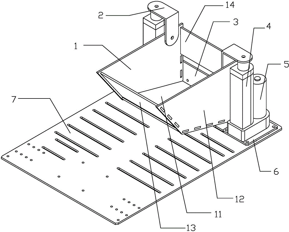
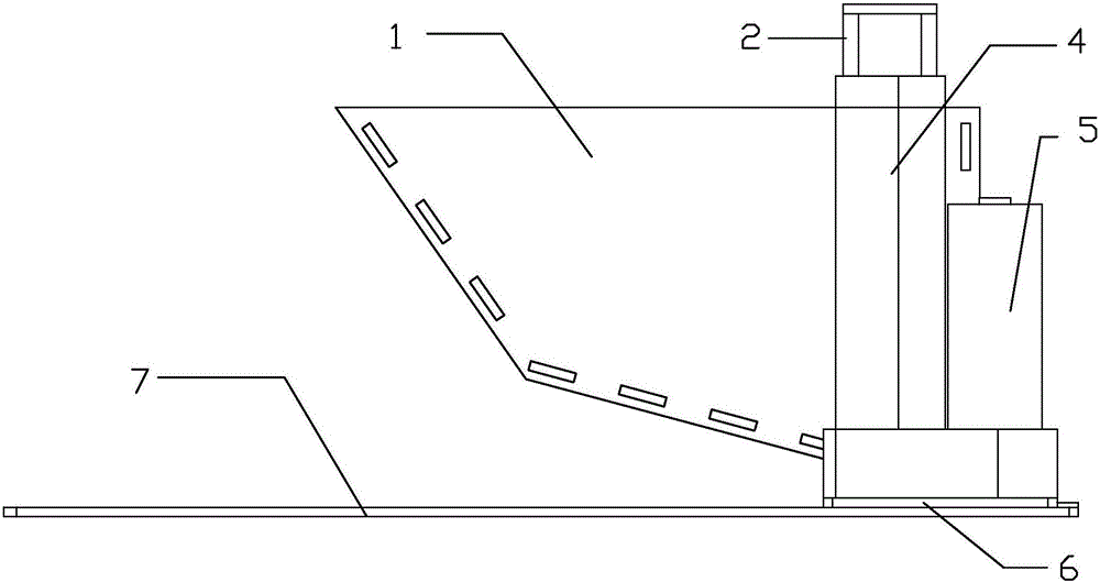
The invention discloses an electric push rod lifting mechanism capable of realizing loading and unloading of cargoes. The electric push rod lifting mechanism comprises push rods (4), stepping motors (5), a storage device (1), a limiting plate (3), a bottom plate (7), L-shaped connection pieces (2) and fixed racks (6), wherein the push rods (4) and the stepping motors (5) are connected with the bottom plate (7) through the fixed racks (6); the storage device (1) is connected with the push rods (4) through the L-shaped connection pieces (2); the limiting plate (3) is fixedly connected with the bottom plate (7) through bolts; and the stepping motor (5) drives the push rods (4) to stretch out and draw back. The electric push rod lifting mechanism is simple and attractive in structure, convenient to install, small in occupation space, low in requirement for working conditions and low in cost and can completely meet the safety technology requirements and the daily use requirements for loading and unloading.

Description

technical field [0001] Aiming at the defects of the existing lifting mechanism, the present invention provides an electric push rod lifting mechanism based on the control of a stepping motor. Background technique [0002] Simplicity and convenience have always been a direction pursued by human beings. In order to make loading and unloading fast and convenient, an automatic lifting structure is used to realize loading and unloading. Commonly used lifting mechanisms include scissor lifting mechanisms, guide rail lifting mechanisms, screw lifting mechanisms, hydraulic lifting mechanisms, electric push rod lifting mechanisms and other lifting mechanisms that can realize lifting functions. Among them, the scissor lift mechanism, such as the patent application number 201510683984.2, describes the scissor lift platform using the cylinder to provide reliable power to achieve lifting, but the production and installation of the scissor lift platform is more troublesome, and the workin...

Claims


Application Information

Patent Timeline
Patent Type & Authority Applications(China)
IPC IPC(8): B66F11/00
CPCB66F11/00
Inventor 许妙平王天雷崔敏耿爱农李辛沫杨庆强陈嘉维苏健强
Owner 江门市蒙德电气股份有限公司
Learn More