Eureka AIR delivers breakthrough ideas for toughest innovation challenges, trusted by R&D personnel around the world.

An inner stator hoisting and turning structure

An inner stator and ring cage technology, which is applied to load hanging components, transportation and packaging, etc., can solve problems such as damage to inner stator products, eccentricity, and inability to turn over, so as to improve the safety factor and service life.

Active Publication Date: 2018-08-14
SHANGHAI ELECTRIC POWER GENERATION EQUIPMENT CO LTD
View PDF6 Cites 0 Cited by
  • Summary
  • Abstract
  • Description
  • Claims
  • Application Information

AI Technical Summary

Problems solved by technology

Its main disadvantages are as follows: 1. If the inner stator ring cage connecting plate is not in the symmetrical position of the center line, it will be eccentric and cannot be lifted vertically. When leaving the station, it will interfere with the station facilities and auxiliary tooling, resulting in damage Inner Stator Products
2. If there is a deflection angle on the connecting plate of the inner stator ring cage, the turning operation cannot be realized
3. The traditional structure is mainly connected by bolts, and the bolts are subjected to shear force during the lifting and turning process
Due to excessive local stress, the threads on the ring cage connecting plate are deformed, which affects the normal withdrawal of the bolts
[0003] For the 660MW double-water internal cooling generator, the ring cage connecting plate is not at the symmetrical position of the center line, and there is still a deflection angle. If the traditional lifting and turning tool structure is used, neither vertical lifting nor turning operation can be realized.

Method used


Image

  • An inner stator hoisting and turning structure
  • An inner stator hoisting and turning structure
  • An inner stator hoisting and turning structure

Examples


Embodiment Construction

[0017] In order to make the present invention more obvious and understandable, the present invention will be further described with preferred embodiments.

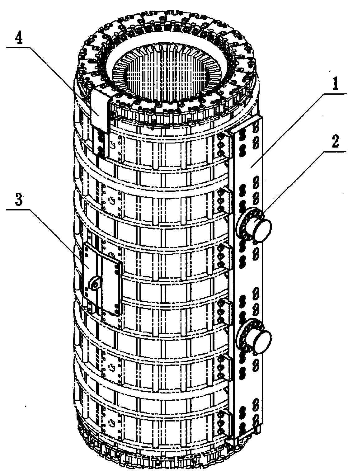
[0018] to combine figure 1 and Figure 7 , in the present invention, the inner stator has a plurality of rings 7 distributed along the axial direction, each ring 7 circles the inner stator in the circumferential direction, and a plurality of ring cage connecting plates 6 are arranged on each ring 7 in the circumferential direction.

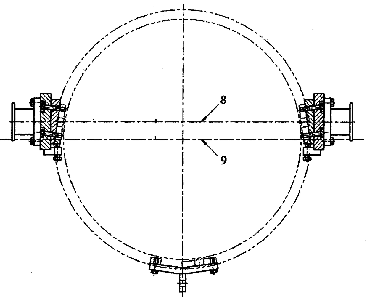
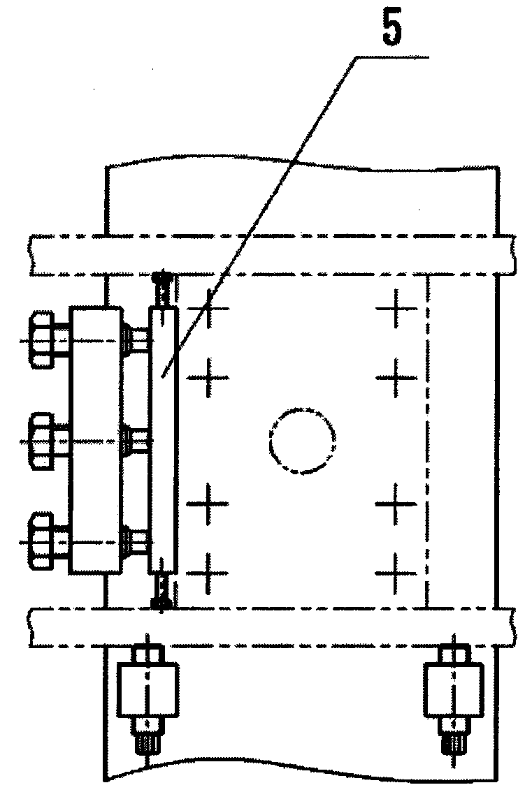
[0019] to combine figure 1 , Figure 3A and Figure 3B , An inner stator hoisting and turning structure provided by the present invention includes a ring cage connecting device 1 , a hanging climber 2 , a small hook lug 3 , a wire rope baffle plate 4 , and a spacer 5 . to combine Figure 4 and Figure 5 , The ring cage connection device 1 includes a long plate 1-1, an inclined pad 1-2, a side tightening structure 1-3 and a tightening structure 1-4.

[0020] The structure of the present ...


PUM


Abstract

The invention provides an inner stator lifting and turnover structure. By the adoption of a structure that a small hook of a travelling crane is matched with a large hook for simultaneous lifting, the inner stator lifting and turnover structure guarantees perpendicular lifting of an inner stator; by the additional arrangement of an inclined base plate structure, the axes of two lifting bars can be located on the same straight line after the inner stator lifting and turnover structure is mounted, so that the requirement of turnover rotation is met; by the additional arrangement of a tightening structure, the inner stator is stressed with both the shearing force of bolts and the forward tightening force of the tightening device in the lifting and rotating turnover process; and therefore, the safety coefficient of the whole structure is greatly increased, and the service life of the whole structure is greatly prolonged.

Description

technical field [0001] The invention relates to a structure for vertical lifting and turning over of the inner stator after the completion of the inner stator in the outer press-fitting process, which is convenient for the subsequent installation of the inner and outer stators. Background technique [0002] The inner stator is an important part of the turbogenerator, which is mainly composed of stator core, vibration isolation ring cage and other components. When assembling the inner stator, the stator core is first installed as a whole, and then the vibration isolation ring cage is positioned and welded firmly on the stator core, so that the two become a whole. The weight of the inner stator of the 660MW double-water internal cooling generator is about 220 tons. Due to the needs of the inner and outer stators, the inner stator structure needs to be lifted vertically and turned over at 90° after completion. The traditional lifting and turning tool structure is to install th...

Claims


Application Information

Patent Timeline
Patent Type & Authority Patents(China)
IPC IPC(8): B66C1/10B66C13/08
CPCB66C1/10B66C13/08
Inventor 茅邓华刘雷丁辉张会涛刘汀张航
Owner SHANGHAI ELECTRIC POWER GENERATION EQUIPMENT CO LTD
Why Eureka
Eureka Blog
Learn More