Independently controllable high-temperature equipment provided with multiple vacuum cavities

A technology for vacuum chambers and storage equipment, which can be used in packaging under vacuum/special atmosphere, packaging objects under special gas conditions, food heating containers, etc. It can solve problems such as equipment cost and energy consumption increase, and inconvenience in testing or production , to achieve the effect of short vacuuming time and large heat radiation area

Inactive Publication Date: 2017-04-26
CHINA ELECTRONICS TECH GROUP CORP NO 16 INST
View PDF10 Cites 2 Cited by
  • Summary
  • Abstract
  • Description
  • Claims
  • Application Information

AI Technical Summary

Problems solved by technology

[0003] At present, vacuum high-temperature storage equipment is mostly designed as a single vacuum chamber, so that a batch of complete machines or parts must be put in or taken out in batches during the test storage process, which will bring great inconvenience to the test or production. ;In order to ensure the test or production node, some vacuum high-temperature storage equipment is designed as multiple vacuum chambers, but each chamber corresponds to a set of vacuum pumping system to ensure that each vacuum chamber does not interfere with each other, which will cause equipment costs and increased energy consumption

Method used


Image

  • Independently controllable high-temperature equipment provided with multiple vacuum cavities
  • Independently controllable high-temperature equipment provided with multiple vacuum cavities
  • Independently controllable high-temperature equipment provided with multiple vacuum cavities

Examples


Embodiment Construction

[0022] The present invention will be described in further detail below in conjunction with the accompanying drawings and specific embodiments.

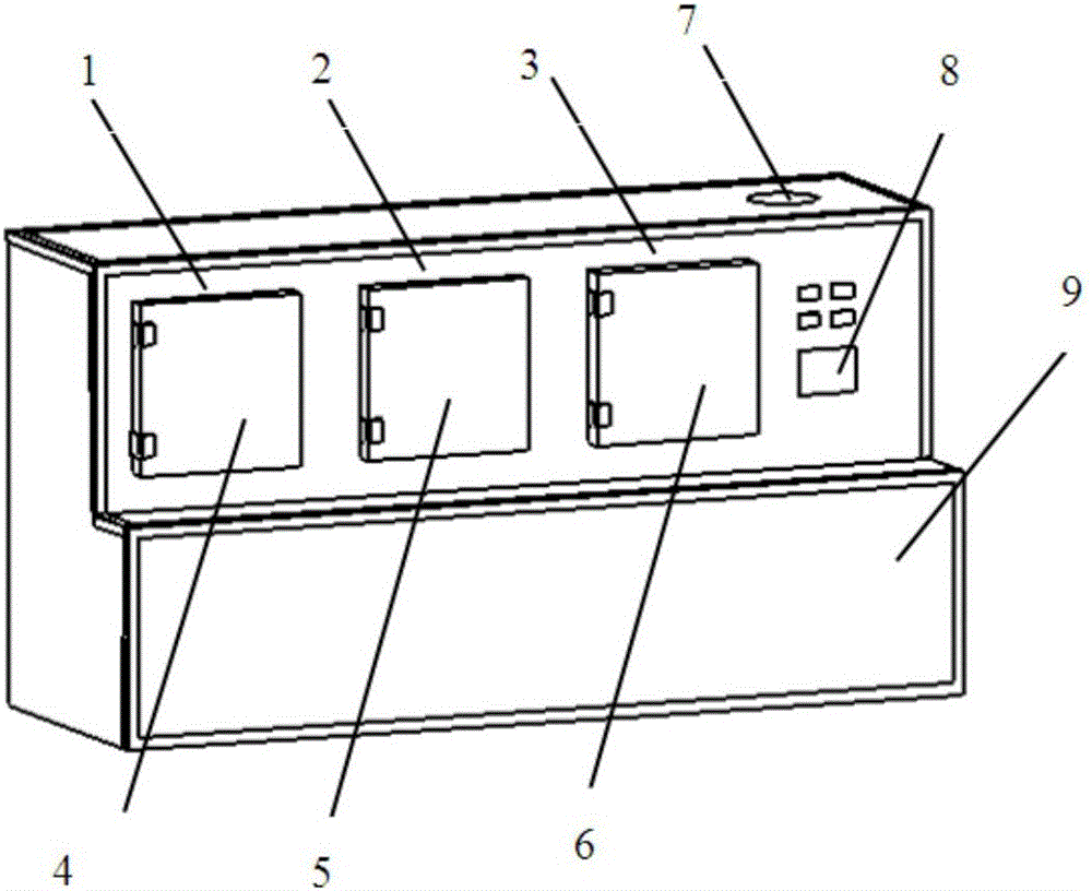
[0023] Such as Figure 1~3 As shown, an independently controllable multi-chamber vacuum high-temperature storage device includes a first vacuum chamber 1, a second vacuum chamber 2, a third vacuum chamber 3, a first airtight door 4, and a second airtight door 5 , the third airtight door 6, vacuum system 7, display control system 8 and cabinet 9;

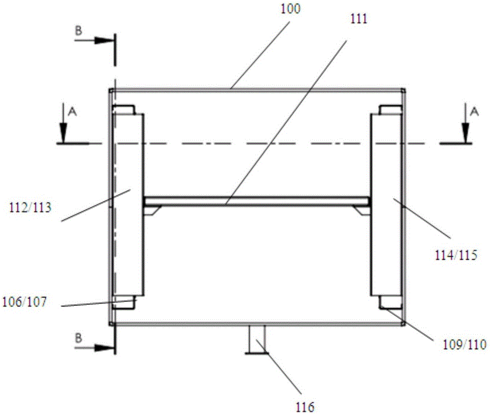
[0024] The left heat radiation chamber 101 is composed of a vacuum chamber stainless steel wall, a left heating tube 104, and a left heat radiation orifice plate 105. The left heating tube 104 is fixed on the left front heating tube fixing frame 106 and the left rear heating tube fixing frame On 107; the right heat radiation chamber 102 is made up of the stainless steel wall of the vacuum chamber, the right heating tube 108, and the right heat radiation orifice 109, and the right heating tu...


PUM


Abstract

The invention discloses independently controllable high-temperature equipment provided with multiple vacuum cavities. The independently controllable high-temperature equipment provided with the multiple vacuum cavities comprises the first vacuum cavity, the second vacuum cavity, the third vacuum cavity, a first sealing door, a second sealing door, a third sealing door, a vacuum-pumping system, a display control system and a cabinet body, wherein the first vacuum cavity, the second vacuum cavity and the third vacuum cavity have the same constitution; each vacuum cavity comprises a left-side heat radiation chamber, a right-side heat radiation chamber and a work chamber positioned between the left-side heat radiation chamber and right-side heat radiation chamber; the vacuum-pumping system consists of a molecular pump, a forepump, a prepump and a vacuum electromagnetic valve; one set of vacuum-pump system can vacuumize the plurality of cavities; the prepump is used for performing first-state vacuumization on the vacuum cavities; the forepump is used for maintain the vacuumizing work of the molecular pump and also can serve as the prepump when necessary; the vacuum time of the whole system is short; and independently controllable high-temperature equipment provided with the multiple vacuum cavities can realize that the plurality of vacuum cavities can be independently controlled and display, can realize single stop and restart operation, and realizes non-interference truly.

Description

technical field [0001] The invention relates to the field of packaging or storage in a vacuum and high-temperature environment after the outgassing treatment of the complete machine or parts, and specifically relates to a high-temperature storage device with multiple vacuum chambers that can be independently controlled. Background technique [0002] Vacuum high-temperature storage equipment is widely used in electronic products, optical parts, food hygiene, medical treatment, scientific research and teaching, industry and other fields. It can provide a vacuum and high temperature conditions for drying, heating and vacuum storage of equipment. Especially in the production and testing of electronic instruments and component products, vacuum high-temperature storage equipment plays an important role. [0003] At present, vacuum high-temperature storage equipment is mostly designed as a single vacuum chamber, so that a batch of complete machines or parts must be put in or taken ...

Claims


Application Information

Patent Timeline
IPC IPC(8): B65D81/20B65D81/34
CPCB65D81/20B65D81/34
Inventor 邱彪马学焕王昆
Owner CHINA ELECTRONICS TECH GROUP CORP NO 16 INST
Why Eureka
Try Eureka