
Vacuum composite die

A composite mold and mold technology, which is applied to household appliances, other household appliances, household components, etc., can solve the problem of mold crushing on the fine surface texture, and achieve the effects of reducing power burden, improving efficiency, and facilitating blanking

Active Publication Date: 2017-04-26
ANHUI KINGPOWER EQUIP & MOLD MFR
View PDF5 Cites 3 Cited by
  • Summary
  • Abstract
  • Description
  • Claims
  • Application Information

AI Technical Summary

Problems solved by technology

However, because the surface of automotive interior products usually has exquisite textures, if the production is carried out by pressing materials, the fine textures on the surface are easily crushed by the upper mold

Method used


Image

  • Vacuum composite die
  • Vacuum composite die
  • Vacuum composite die

Examples


Embodiment Construction

[0023] The present invention will be described in further detail below in conjunction with the accompanying drawings.

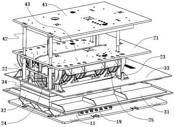
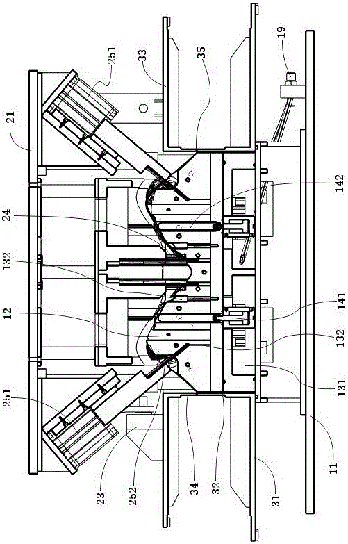
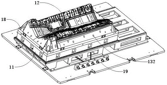
[0024] A vacuum composite mold, such as figure 1 , figure 2 As shown, it includes a mold mechanism, a trimming mechanism, a clamping mechanism and a leather pressing mechanism. The clamping mechanism includes a lower clamping mechanism and an upper clamping mechanism. The lower clamping mechanism includes a lower clamping mounting frame plate 31 and a lower clamping frame 32 . The lower clamping mounting frame plate 31 is horizontally arranged. The lower clamping frame 32 has a square structure, surrounds the mold 12 and is installed on the lower clamping mounting frame 31 . The upper clamping mechanism includes an upper clamping mounting frame plate 33 and an upper clamping frame 34 . The upper folder mounting frame plate 33 is horizontally arranged. The upper clamping frame 34 is installed below the upper clamping mounting frame plate 33 . The upper...


PUM


Abstract

The invention discloses a vacuum composite die which comprises a die mechanism, a trimming mechanism and a clamping mechanism. The die mechanism comprises a die mounting rack and a die. An outer cutter groove, an inner cutter groove and a vacuum passage are formed in the die. The die mounting rack is provided with a vacuum pipeline and a vacuum pipeline connector, wherein the vacuum pipeline and the vacuum pipeline connector are connected with the vacuum passage. The trimming mechanism comprises a tool mounting frame plate, tool supporting columns, an inner trimming blade and an outer trimming mechanism body. The tool supporting columns, the inner trimming blade and the outer trimming mechanism body are installed below the tool mounting frame plate. The outer trimming mechanism body comprises an outer trimming air cylinder and an outer trimming blade. The clamping mechanism comprises a lower clamping frame and an upper clamping frame, and the upper clamping frame and the lower clamping frame are matched in dimension. The upper clamping frame is installed below the tool mounting frame plate through a lifting buffer connection mechanism. By means of the lifting buffer connection mechanism, when the trimming mechanism is pressed downwards for trimming, the upper clamping frame is pressed on the lower clamping frame firstly, and then the inner trimming blade conducts trimming on leather.

Description

technical field [0001] The invention relates to a vacuum composite mould. Background technique [0002] Many interior parts of automobiles are made of hard plastic skeleton and outer leather layer. For example, the interior of a car door. Composite molds are equipment for producing such automotive interior parts. Firstly, the skeleton is placed on the mold, and then the heated and softened leather is spread on the skeleton, and the leather is pasted on the skeleton by using the viscosity generated on the surface of the leather after heating and softening, and then the edges are trimmed. The composite mold in the prior art is usually formed by pressing the upper mold and the lower mold. However, since the surface of automotive interior products usually has exquisite textures, if the production is carried out by pressing materials, the fine textures on the surface are easily crushed by the upper mold. Contents of the invention [0003] The problem to be solved by the pre...

Claims


Application Information

Patent Timeline
Patent Type & Authority Applications(China)
IPC IPC(8): B29C51/30B29C51/36B29C51/32B29C51/42B29C51/44B29L31/58
CPCB29C51/30B29C51/32B29C51/36B29C51/428B29C51/44B29L2031/58
Inventor 陈义兵卫正坤
Owner ANHUI KINGPOWER EQUIP & MOLD MFR
Learn More