
Steam turbine, and method for operating a steam turbine

A steam turbine, flow direction technology, applied in the direction of machines/engines, mechanical equipment, etc., can solve expensive and other problems, and achieve the effect of good cooling feasibility

Inactive Publication Date: 2017-04-19
SIEMENS AG
View PDF6 Cites 3 Cited by
  • Summary
  • Abstract
  • Description
  • Claims
  • Application Information

AI Technical Summary

Problems solved by technology

Without effective cooling, significantly more expensive materials are required at elevated temperatures (e.g., nickel-based alloys)

Method used


Image

  • Steam turbine, and method for operating a steam turbine
  • Steam turbine, and method for operating a steam turbine

Examples


Embodiment Construction

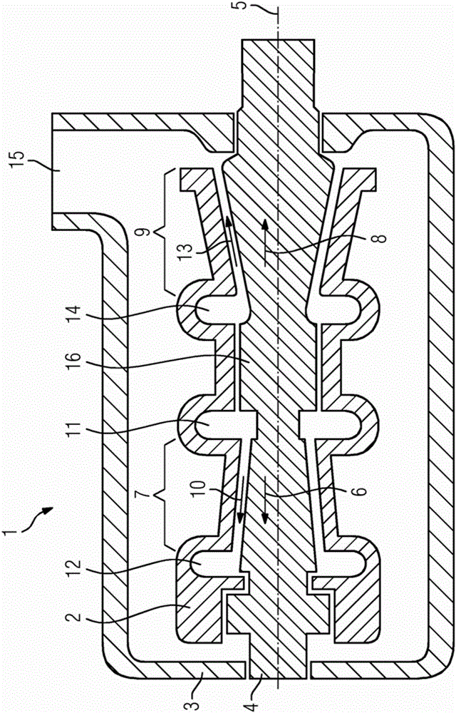
[0034] figure 1A steam turbine 1 is shown, which comprises an inner housing 2 and an outer housing 3 as well as a rotor 4 . The rotor 4 is rotatably mounted within the inner housing 2 . The means of support are not shown in detail. The outer casing 3 is arranged around the inner casing 2 . The rotor 4 is substantially rotationally symmetrical about the axis of rotation 5 . Along a first flow direction 6 running substantially parallel to the axis of rotation 5 , the rotor 4 has a high-pressure region 7 . Arranged opposite to the first flow direction 6 , the rotor 4 has a medium-pressure region 9 which is arranged along the second flow direction 8 .

[0035] In the high-pressure region 7 , the inner housing 2 has a plurality of high-pressure guide vanes (not shown), which are arranged on the circumference around the axis of rotation 5 . The high-pressure guide vanes are arranged such that along the first flow direction 6 a high-pressure flow channel 10 is formed with a plur...


PUM


Abstract

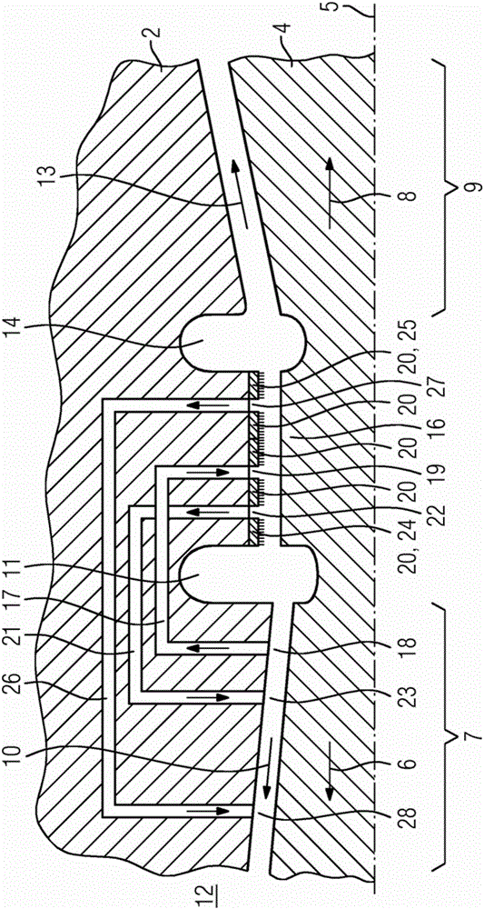
The invention relates to a steam turbine (1) having a cooling option, in which steam is taken from the flow channel, said steam cooling the thrust-compensating intermediate floor (16), being mixed with a small amount of live steam and being returned to the flow channel.

Description

technical field [0001] The invention relates to a steam turbine comprising an inner casing and an outer casing and a rotor, the rotor being arranged in a rotatable manner within the inner casing, wherein the outer casing is arranged around the inner casing, wherein the rotor has A high-pressure region arranged along the first flow direction and a medium-pressure region arranged along the second flow direction. [0002] Furthermore, the invention relates to a method for cooling a steam turbine, wherein the steam turbine has a high-pressure region and an intermediate-pressure region, wherein a rotor is arranged between the high-pressure region and the intermediate-pressure region and has a thrust-balancing diaphragm. Background technique [0003] Within the scope of this application, a steam turbine is understood to mean a turbine or a turbine section through which a working fluid in the form of steam flows. Unlike here, gas turbines have gas and / or air flowing through them a...

Claims


Application Information

Patent Timeline
Patent Type & Authority Applications(China)
IPC IPC(8): F01D3/02F01D3/04
CPCF01D3/02F01D3/04F05D2220/31F05D2260/2322F05D2240/56F01D25/26F01D25/12
Inventor 扬·沃克浩斯特乌韦·赞德阿尔明·德拉泽尔
Owner SIEMENS AG
Learn More