
Wireless grid building method and base station

A base station and wireless technology, applied in the field of communication, can solve the problems that the wireless grid cannot locate the UE, and the number of downlink adjacent cells is limited, so as to achieve the effect of accurate wireless grid and improved positioning

Active Publication Date: 2017-04-19
SHANGHAI HUAWEI TECH CO LTD
View PDF5 Cites 19 Cited by
  • Summary
  • Abstract
  • Description
  • Claims
  • Application Information

AI Technical Summary

Problems solved by technology

However, in an actual network, due to the measurement capability of the UE and the mutual interference between neighbors, the number of downlink neighbors measured by the UE in the serving cell / near point is very limited, and the RSRP of the cell measured in a large part of the cell is Number ≤ 2, in this case the wireless grid cannot accurately locate the UE

Method used


Image

  • Wireless grid building method and base station
  • Wireless grid building method and base station
  • Wireless grid building method and base station

Examples


Embodiment Construction

[0052] Embodiments of the present invention provide a method for constructing a wireless grid and a base station, which are used to improve the positioning of a UE's position.

[0053] The following will clearly and completely describe the technical solutions in the embodiments of the present invention with reference to the accompanying drawings in the embodiments of the present invention. Obviously, the described embodiments are only some, not all, embodiments of the present invention. The terms "first", "second", "third", "fourth", etc. (if any) in the description and claims of the present invention and the above drawings are used to distinguish similar objects, and not necessarily Used to describe a specific sequence or sequence. It is to be understood that the terms so used are interchangeable under appropriate circumstances such that the embodiments described herein can be practiced in sequences other than those illustrated or described herein. Furthermore, the terms "co...


PUM


Abstract

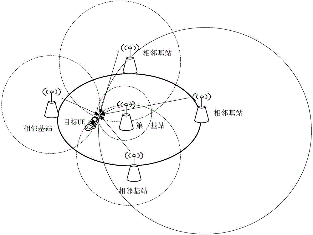
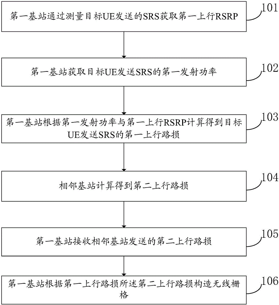
The embodiment of the invention discloses a wireless grid building method comprising the following steps: a first base station measures a sensing reference signal SRS sent by target user equipment UE so as to obtain a first uplink reference signal reception power RSRP, wherein the target UE refers to the UE in a service community to which the first base station is located; the first base station obtains the first emission power of the target UE sending the SRS; the first base station calculates the first uplink path loss of the target UE sending the SRS according to the first emission power and the first uplink RSRP; the first base station receives second uplink path losses sent by adjacent base stations; the first base station builds the wireless grid according to the first and second uplink path losses. The base station has much stronger receive and measuring ability when compared with the UE; normally the information sent by single UE can be received by a plurality of surrounding base stations, so the base station can obtain the UE uplink path losses so as to build the wireless grid with more accuracy, thus improving UE location positioning.

Description

technical field [0001] The invention relates to the communication field, in particular to a method for constructing a wireless grid and a base station. Background technique [0002] Due to the popularity of smart phones and the development of mobile network services, the amount of communication data in Long Term Evolution (English abbreviation: Long Term Evolution, English abbreviation: LTE) wireless network (4G) is increasing, and the communication capacity that a single wireless frequency band can provide is limited. Therefore, operators usually provide greater communication capacity by adding more wireless frequency bands. Due to the frequency difference and deployment difference of different wireless frequency bands, the channel quality of different wireless frequency bands in the same place may vary greatly. Therefore, the user equipment (English full name: User Equipment, English abbreviation: UE) needs to measure the channel quality of each frequency band. However, d...

Claims


Application Information

Patent Timeline
Patent Type & Authority Applications(China)
IPC IPC(8): H04W24/00H04W64/00
CPCH04W24/00H04W64/00
Inventor 黄黎张浩孙铭扬杨迥迥
Owner SHANGHAI HUAWEI TECH CO LTD
Learn More