Eureka AIR delivers breakthrough ideas for toughest innovation challenges, trusted by R&D personnel around the world.

Forced oscillation disturbance source positioning method based on frequency band-dividing parallel computation

A technology of disturbance source localization and parallel computing, applied in the direction of reducing/preventing power oscillation, fault location, detecting faults by conductor type, etc., can solve problems such as non-coverage

Active Publication Date: 2017-04-19
NARI TECH CO LTD +2
View PDF6 Cites 6 Cited by
  • Summary
  • Abstract
  • Description
  • Claims
  • Application Information

AI Technical Summary

Problems solved by technology

[0011] Purpose of the invention: In order to overcome the deficiencies in the prior art, the present invention provides a forced oscillation disturbance source location method based on frequency-divided parallel computing, aiming at the ultra-low frequency or ultra-high frequency forced power oscillation and PMU measurement points that appear in the actual power grid The problem that the plant station where the disturbance source is located cannot be covered. The design of the scheme is reasonable, which can ensure the timeliness of the forced power oscillation alarm and the location information of the disturbance source

Method used


Image

  • Forced oscillation disturbance source positioning method based on frequency band-dividing parallel computation
  • Forced oscillation disturbance source positioning method based on frequency band-dividing parallel computation
  • Forced oscillation disturbance source positioning method based on frequency band-dividing parallel computation

Examples


Embodiment

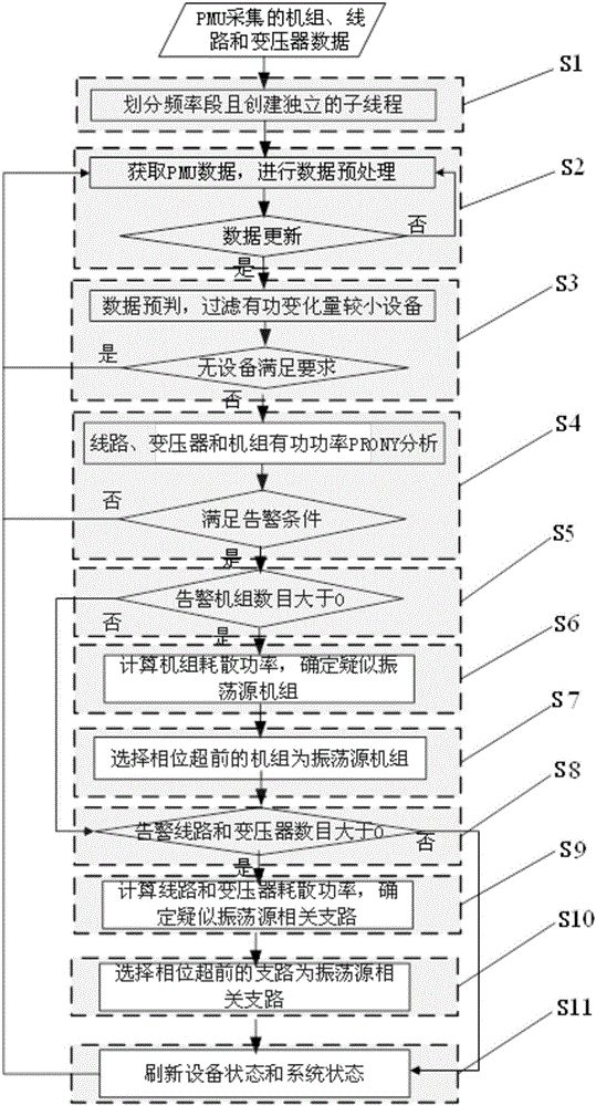
[0092] read on figure 1 , figure 1 In the description of S1, the monitoring frequency is divided into several frequency segments according to the preset frequency range, and sub-threads corresponding to each frequency segment are created for analysis and calculation. The analysis and calculation time of PRONY is strongly related to the number of data points in the data window. The frequency segment analysis and calculation method avoids setting a long observation time window length and a high sampling frequency at the same time, resulting in slow calculation speed. Each sub-thread adopts an asynchronous calculation method without interfering with each other. Set the calculation parameters according to the frequency range of the corresponding frequency segment: Each frequency segment needs to set its own observation time window length and sampling frequency to reduce the number of analysis data points. Different frequency segment signals have different oscillation periods, and ...


PUM


Abstract

The invention belongs to the technical field of power systems and automation thereof, and discloses a forced oscillation disturbance source positioning method based on frequency band-dividing parallel computation. A preset frequency range is divided into a plurality of frequency bands for parallel computation; as for each frequency band, through setting each data window length and each sampling frequency, analyzed data points are reduced; each frequency band adopts an asynchronous computation mode, other frequency bands do not need to be waited after one-round analysis computation, a result is refreshed and new data are obtained for next-round analysis, dissipation power of a unit, a transformer and a line is calculated, a suspected oscillation source related element is screened according to a threshold value, oscillation elements are grouped according to a dominant mode phase angle, and elements with advanced phases in the group of the suspected oscillation source elements are selected as the oscillation source unit, the related line and the transformer. The scheme is reasonably designed, and forced power oscillation warning and disturbance source positioning information timeliness can be ensured.

Description

technical field [0001] The invention belongs to the technical field of electric power system and automation thereof, and in particular relates to a method for locating a forced oscillation disturbance source based on frequency-divided parallel calculation. Background technique [0002] With the strengthening of the grid structure of the power system and the improvement of various damping control devices in the system, the traditional weakly damped low-frequency oscillation has rarely occurred, and forced oscillation has become the main form of low-frequency oscillation accidents. Forced oscillation has the characteristics that the disturbance source is clear, and the system oscillation can automatically calm down after the disturbance is eliminated. Locating the disturbance source and separating the disturbance source from the system are effective means to suppress forced oscillation. [0003] With the promotion of the WAMS system in my country's power grid, the high-voltage...

Claims


Application Information

Patent Timeline
IPC IPC(8): H02J3/24G01R31/08
CPCG01R31/086H02J3/24Y02E60/00
Inventor 鲍颜红姚海成徐泰山周剑杨君军吴云亮刘韶峰张建新任先成李智勇
Owner NARI TECH CO LTD
Why Eureka
Eureka Blog
Learn More