A Multi-DOF Spectral Filter Compensating for Polarization Mode Dispersion
A technology of polarization mode dispersion and spectral filter, which is applied in the direction of instruments, optics, static indicators, etc., can solve the problems of difficult adjustment of free spectral region, complex adaptive control system, etc., and achieve the effect of suppressing the effect of amplitude-frequency modulation
- Summary
- Abstract
- Description
- Claims
- Application Information
AI Technical Summary
Problems solved by technology
Method used
Image
Examples
Embodiment 1
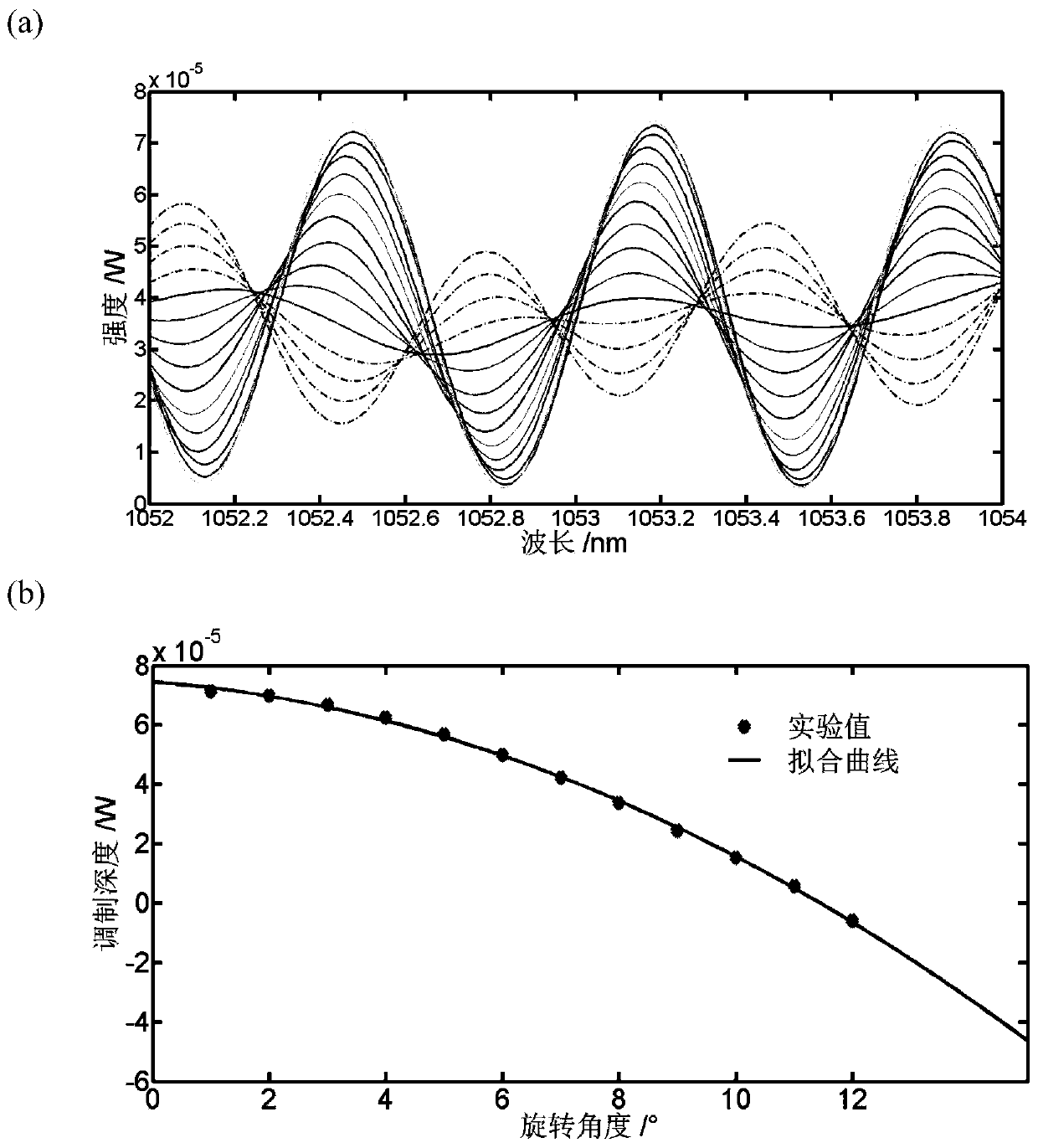
[0023] Embodiment 1: as attached figure 1 As shown, a multi-degree-of-freedom spectral filter that can compensate polarization mode dispersion includes a fiber collimator 1 with a central wavelength of 1053nm, a film polarizer 2 with a transmission wavelength of 550-1500nm, and a clear aperture Half-wave phase liquid crystal with a transmission wavelength of 1050-1700nm 3, a second optical fiber collimator whose pigtail is a 1053nm polarization-maintaining fiber 4, an additional polarization-maintaining fiber with a transmission wavelength of 1053nm 5, a polarization-maintaining fiber spliced after the optical axis is rotated by 45° Polarized optical fiber 6 and optical fiber analyzer 7 whose pigtail is 1053nm polarization-maintaining optical fiber.
[0024] When the group velocity dispersion and loss introduced by the optical fiber are not considered, the system filter function of the filter can be expressed as
[0025] h out (f)=M ILP M CON M PM-R-PM M CON M PM M ...
Embodiment 2
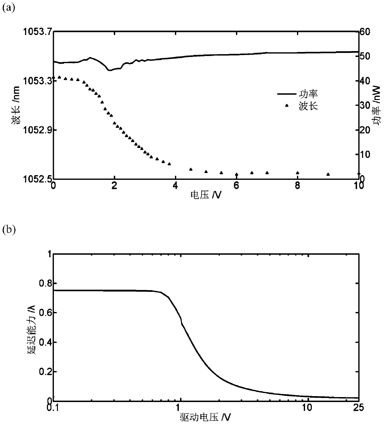
[0034] Embodiment 2: Investigate the peak wavelength decoupling tuning capability of the filter. The implementation conditions are the same as in Example 1, but the angle of the film polarizer is kept constant, and the length of the additional polarization-maintaining fiber is 3 m. Gradually increase the voltage value applied to the liquid crystal, and obtain the schematic diagram of the change of the peak wavelength and peak power of the filter with the liquid crystal voltage as attached image 3 shown. It can be seen from the figure that during the adjustment, the peak power of the filter hardly changes, indicating that the modulation depth does not change with the liquid crystal voltage, that is, the decoupling tuning of the peak wavelength is realized. image 3 (a) is the change curve of peak wavelength and peak power with liquid crystal pressure; image 3 (b) is the variation curve of liquid crystal retardation performance with applied voltage. Comparing the two curves...
Embodiment 3
[0035] Embodiment 3: Investigate the change of the free spectral range of the filter with the change of the length of the additional polarization-maintaining fiber. The implementation conditions are the same as in Example 1, but the angle of the film polarizer and the voltage value applied by the liquid crystal are kept constant, and different additional polarization-maintaining fiber lengths are replaced to obtain a schematic diagram of the change of the peak wavelength and peak power of the filter with the voltage of the liquid crystal as attached Figure 4 shown. The required additional polarization-maintaining fiber length can be calculated according to the formula: Δν=1 / εl according to the required free spectral range, and the conversion relationship when the free spectral range is expressed by frequency and wavelength satisfies: In use, it should be noted that l in the formula is the sum of the total lengths of the second collimator pigtail, the additional polarization-...
PUM
 Abstract
Description
Claims
Application Information
 - R&D Engineer
- R&D Manager
- IP Professional
- Industry Leading Data Capabilities
- Powerful AI technology
- Patent DNA Extraction
Browse by: Latest US Patents, China's latest patents, Technical Efficacy Thesaurus, Application Domain, Technology Topic, Popular Technical Reports.
© 2024 PatSnap. All rights reserved.Legal|Privacy policy|Modern Slavery Act Transparency Statement|Sitemap|About US| Contact US: help@patsnap.com


