Rail transit stray current detection method and detection system

A rail transit and stray current technology, applied in the field of rail transit, can solve problems such as poor result accuracy, and achieve the effect of improving detection accuracy

Active Publication Date: 2017-04-19
深圳市科安达轨道交通技术有限公司
View PDF12 Cites 13 Cited by
  • Summary
  • Abstract
  • Description
  • Claims
  • Application Information

AI Technical Summary

Problems solved by technology

[0005] In summary, the purpose of the present invention is to solve the technical deficiency of the existing stray current detection method due to local measurement and poor measurement accuracy, and propose a stray current detection method for rail transit

Method used


Image

  • Rail transit stray current detection method and detection system
  • Rail transit stray current detection method and detection system
  • Rail transit stray current detection method and detection system

Examples


Embodiment Construction

[0017] The method for detecting stray current of the present invention will be further described below in conjunction with the accompanying drawings and preferred specific embodiments of the present invention.

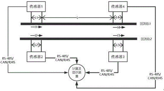
[0018] As we all know, the running rail of a section of subway contains two parallel return rails. In order to form a complete traction power supply circuit, the two return rails need to be connected to the traction substation through return lines respectively; When entering the detected running rail but not entering the detection area, four current sensors are used to detect the current values ​​of the preset sections at both ends of the two return rails of the running rail, and the four current values ​​are sent to the processing module through synchronous communication. The processing module compares the sum of the current values ​​of the two sensors at one end of the two return rails with the sum of the current values ​​of the two sensors at the other end of the two...


PUM


Abstract

The invention discloses a rail transit stray current detection method and a detection system, which relate to the technical field of rail transit and solve the technical defect that local measurement by the existing stray current detection method results in poor measurement result precision. Through four current sensors, current values in preset sections at two ends of two return current rails of an operating rail are detected respectively, the four current values synchronously communicate to a processing module respectively, the processing module compares the current value sum of two sensors at one end of the two return current rails and the current value sum of two sensors at the other end of the two return current rails, a difference is calculated, the difference is the rail transit stray current value, the processing module outputs the rail transit stray current value to a display module, and the rail transit stray current value is displayed. The difference is calculated according to the current values at two ends, the rail transit stray current value is thus obtained, the subway stray current is thus analyzed comprehensively on the whole, and the stray current detection accuracy is improved.

Description

technical field [0001] The invention relates to the technical field of rail transit, in particular to a method for detecting stray currents in rail transit. Background technique [0002] In rail transit, especially in the subway system, the running rail is not only used to bear the load of the vehicle, but also serves as the return rail of the traction power supply system, that is, the running rail is connected to the traction substation through the return line to form a complete Traction power supply circuit. [0003] As the return rail of the traction power supply system, the running rail is very easy to generate stray current. The reason for the stray current is: generally the catenary is the positive pole, and the running rail doubles as the return line. Due to the electrical impedance of the return rail, the traction current produces a voltage drop in the return rail. Since the running rail cannot be completely insulated from the ground, there is a potential differenc...

Claims


Application Information

Patent Timeline
Patent Type & Authority Applications(China)
IPC IPC(8): G01R19/25
CPCG01R19/2513
Inventor 张帆杨士光刘卫国何远进穆志维
Owner 深圳市科安达轨道交通技术有限公司
Why Eureka
Try Eureka