Button device and light guide element

A light-guiding element and key technology, which is applied to electrical elements, emergency protection devices, legends, etc., can solve the problems of increasing the manufacturing cost of a light-emitting keyboard, reducing the light uniformity of the light-emitting keyboard, and it is difficult to balance the manufacturing cost and light uniformity. Taking into account light uniformity, taking into account the effect of manufacturing cost and reducing dosage

Active Publication Date: 2018-08-10
GIGA BYTE TECH CO LTD
View PDF4 Cites 0 Cited by
  • Summary
  • Abstract
  • Description
  • Claims
  • Application Information

AI Technical Summary

Problems solved by technology

[0003] However, it is generally difficult to balance the manufacturing cost and light uniformity of the luminous keyboards currently on the market. The reason is that if you want to improve the light uniformity of the luminous keyboards, you must increase the number of light sources, but the increase in the number of light sources will increase the brightness of the luminous keyboards. manufacturing cost
Conversely, if the number of light sources is reduced, although the manufacturing cost of the luminous keyboard can be reduced, the light uniformity of the luminous keyboard will be reduced.
Therefore, the luminous keyboards currently on the market have the problem of difficulty in balancing the manufacturing cost and the uniformity of light.

Method used


Image

  • Button device and light guide element
  • Button device and light guide element
  • Button device and light guide element

Examples


Embodiment Construction

[0039] Below in conjunction with accompanying drawing, structural principle and working principle of the present invention are specifically described:

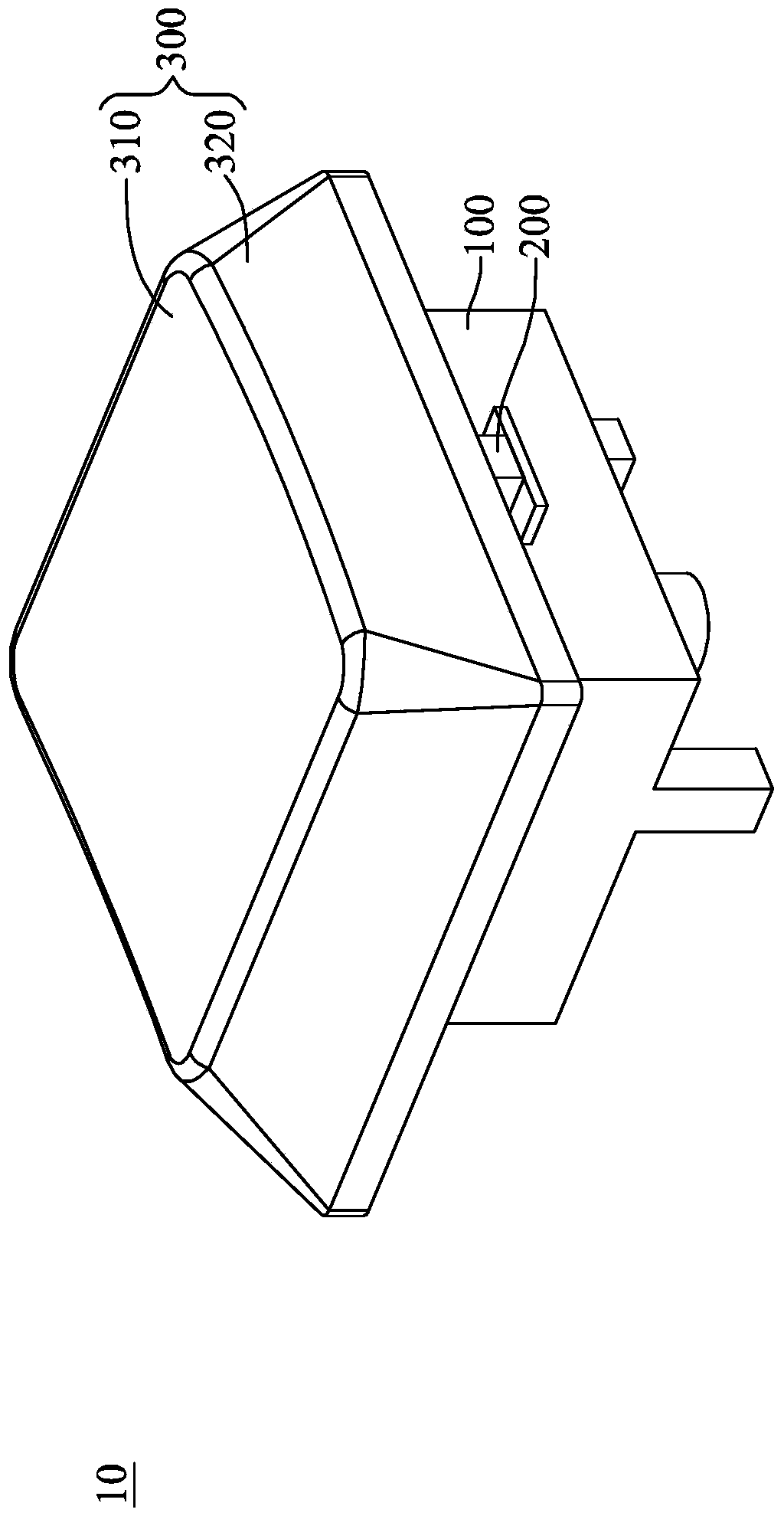
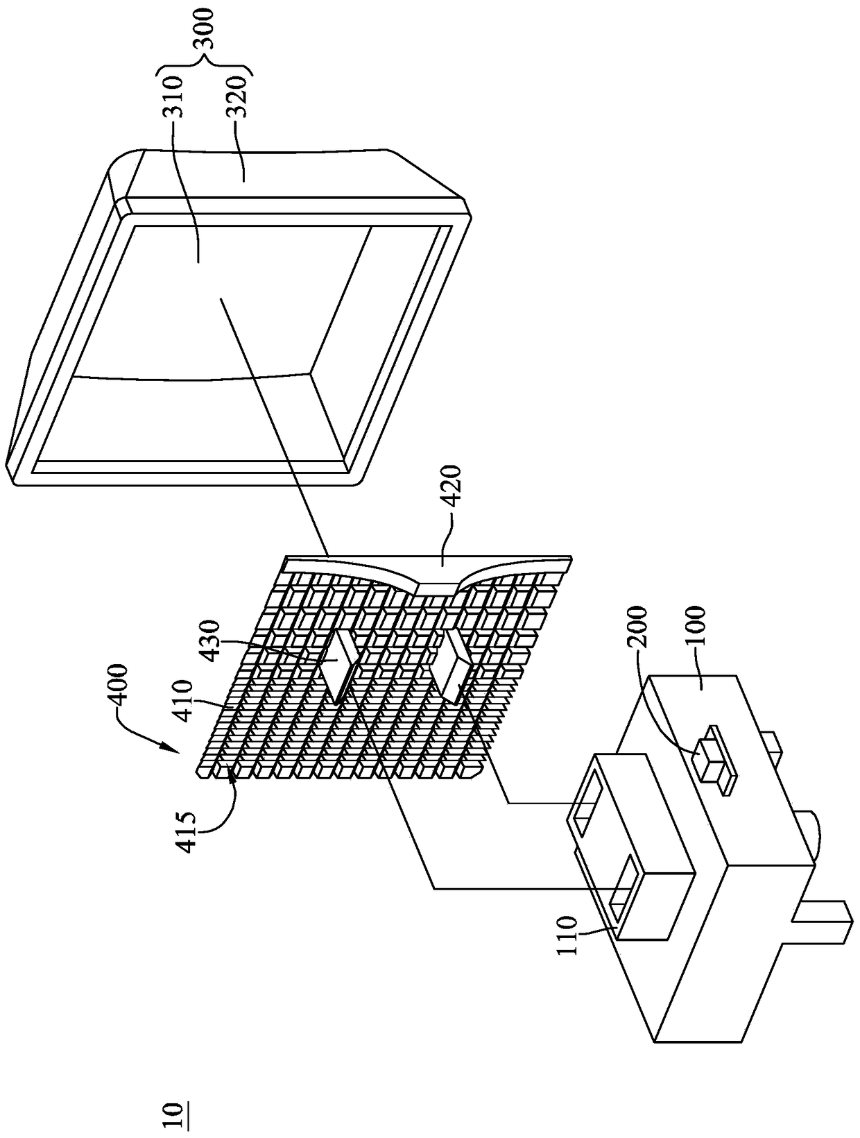
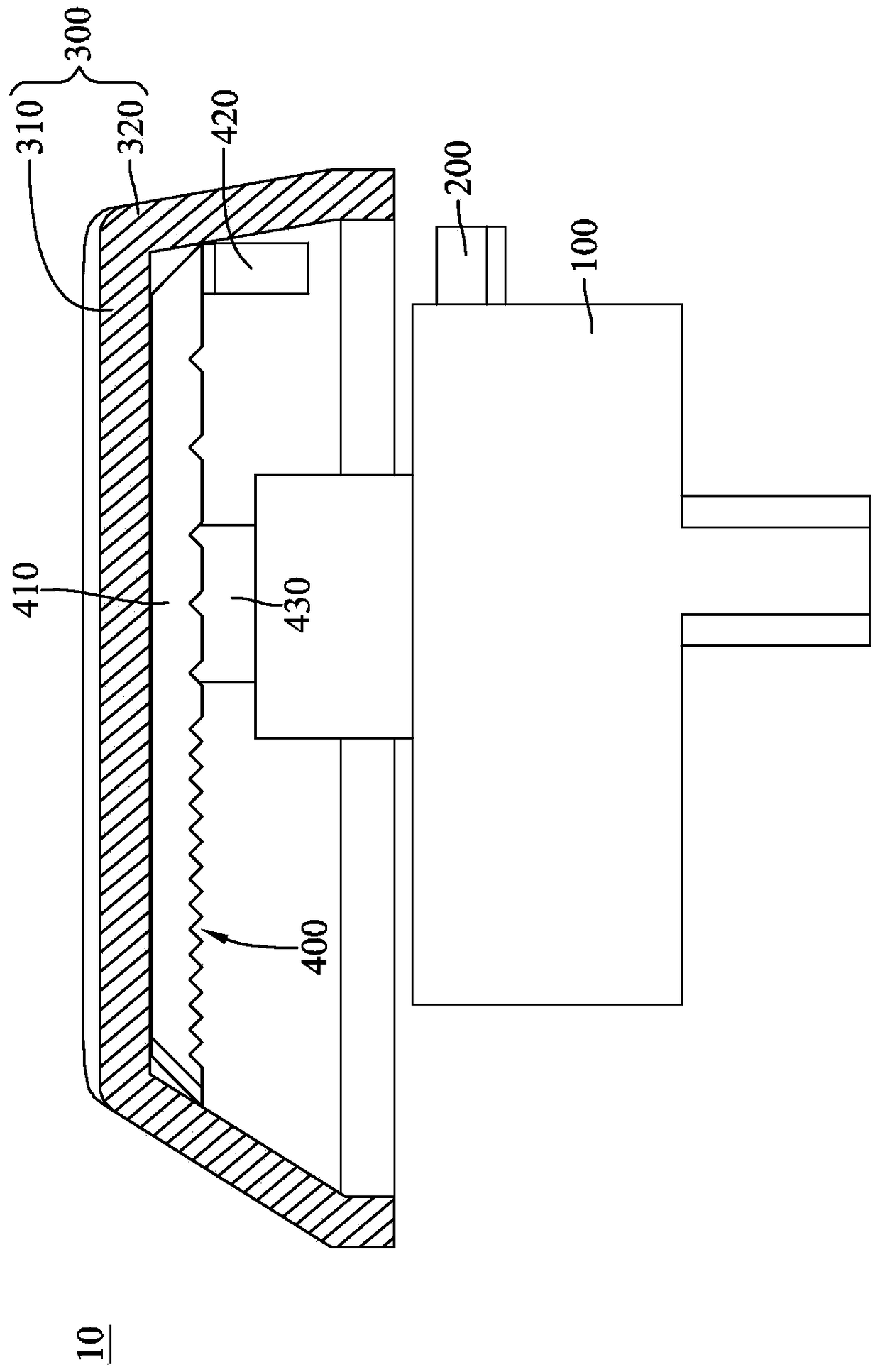
[0040] see Figure 1 to Figure 3 . figure 1 It is a three-dimensional schematic view of the button device according to the first embodiment of the present invention. figure 2 for figure 1 The decomposition diagram. image 3 for figure 1 sectional schematic diagram.

[0041] The key device 10 of this embodiment is suitable for a luminous keyboard (not shown), which includes a key switch 100 , a light source 200 , a key cap 300 and a light guide element 400 . In addition, a bridging bridge (such as a scissor-type pivot structure, not shown) may be further provided in the button device 10 . Since bridging is not the key point of the present invention and is a technology already known to those skilled in the art, the structures related to bridging will not be repeated here.

[0042] The key switch 100 is, for example, a me...


PUM


Abstract

The invention discloses a keypress apparatus and a light-conducting element. The keypress apparatus includes a keypress switch, a light source, a key cap and a light-conducting element. The light source is close to the keypress switch. The key cap covers the keypress switch and the light source. The key cap includes a light-transmitting plate part and a side plate part. The side plate part is connected to the light-transmitting plate part and surrounds the light source. The light-conducting element is disposed between the light-transmitting plate part and the light source. The light-conducting element includes an even light plate part and a light introducing part. The even light plate part has a light-emitting surface and a back surface. The light-emitting surface faces the light-transparent plate part of the key cap. The light introducing plate part has one connecting surface and one light incident surface which are in opposite arrangement. The connecting surface is connected to the back surface of the even light plate part and is connected to one side edge of the back surface. The light source is close to the light incident surface side of the light introducing part, and the connecting surface of the light introducing plate part is longer than the light incident surface of the light introducing plate part in length.

Description

technical field [0001] The invention relates to a key device and a light guide element, in particular to a key device and a light guide element with luminous effects. Background technique [0002] In today's technologically advanced information age, computers have become an indispensable necessity for people. As far as the current computer is concerned, the keyboard is one of the indispensable input devices for inputting characters, symbols or numbers. When a user selects a keyboard, in addition to considering the function of the keyboard, the visual effect of the appearance of the keyboard is also valued by the user. For example, luminous keyboards have been launched on the market at present, in order to attract users by creating cool visual effects through lights. In addition, when the user uses the luminous keyboard at night or in a place with insufficient lighting, the light source provided by the luminous keyboard itself can also help the user find the keys, so as to ...

Claims


Application Information

Patent Timeline
Patent Type & Authority Patents(China)
IPC IPC(8): H01H13/83
CPCH01H13/83H01H2219/056H01H2219/062
Inventor 何瑞峰王嫚君
Owner GIGA BYTE TECH CO LTD
Why Eureka
Try Eureka