
Patsnap Eureka
For R&D, Patsnap Eureka makes reading and utilizing patents & technical documents easy.
Patsnap Eureka AIR
Designed for self-driven R&D workflows. Generate viable solutions, solve complex R&D challenges, empower your innovation with AI.

Patsnap Eureka Materials
Designed for material experts only. Revolutionize your material R&D, from search, analyze, to developing new materials.

TechResearch
Generate reliable direction feasibility study reports for your R&D in just a few steps.

TechSeek
Discover and master advanced knowledge NOW. Basics, ideas, possibilities, all at once.

TechMind
As an expert in R&D Theories, TechMind can generates customized viable solutions instantly.

TechRisk
Analyze your overall solution with one click, know your potential R&D risks in advance.

TechMonitor
Get weekly tech updates, stay abreast of the latest tech innovations and key insights.
Cutter device and printer using same
A technology of cutter and printing device, applied in printing device, printing and other directions, can solve problems such as inconvenience of operation, and achieve the effect of simple structure, strong usability, and improved switching speed
- Summary
- Abstract
- Description
- Claims
- Application Information
AI Technical Summary
Problems solved by technology
Method used
Image

Examples
Embodiment Construction
[0052] The technical solutions of the present invention will be further described below in conjunction with the accompanying drawings and through specific implementation methods.
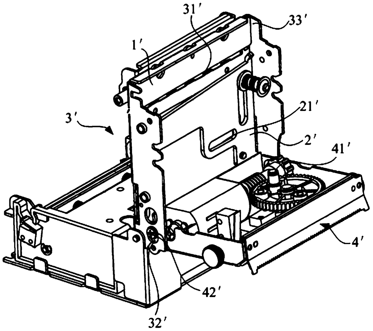
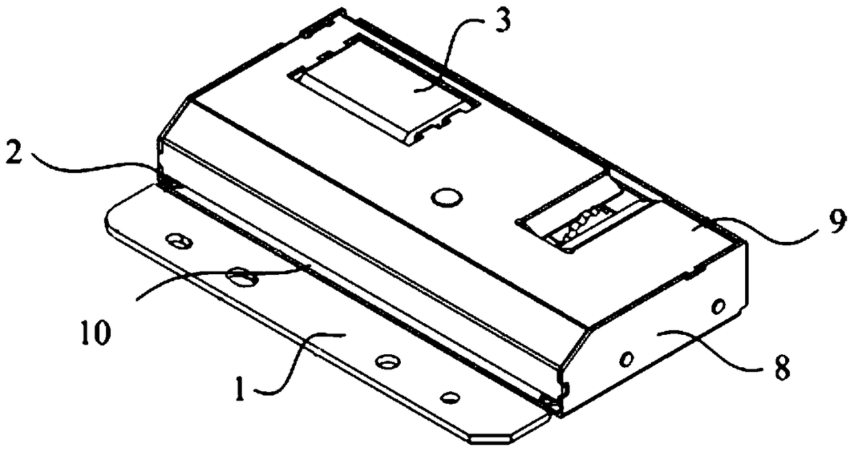
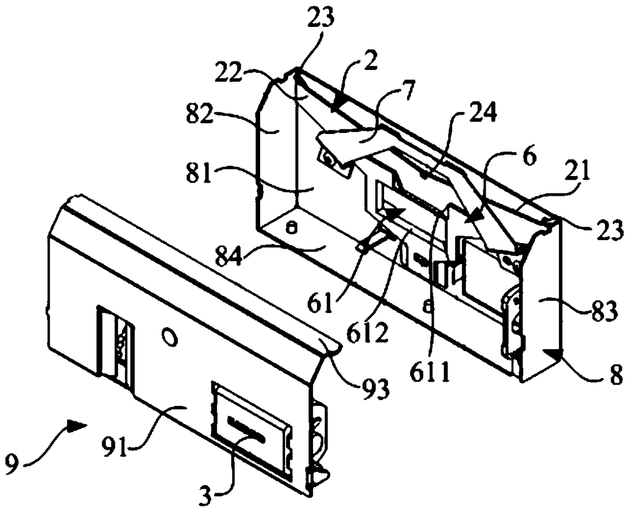
[0053] Such as Figures 2 to 7 As shown, the embodiment of the present invention provides a cutting device, including: a fixed blade 1 and a movable blade 2, and also includes a drive assembly 3 and a transmission assembly 4 for connecting the movable blade 2 and the drive assembly 3, the transmission assembly 4 It includes a bidirectionally rotatable drive shaft 43, a drive pin 42 connected to the drive shaft 43, and a cam 41 that is plugged in with the drive shaft 43 and driven by the drive pin 42, wherein when the drive assembly 3 drives the drive shaft 43 with the first When rotating in one direction, the first outer edge 413 of the cam 41 drives the movable blade 2 to move in the first stroke, and when the drive assembly 3 drives the drive shaft 43 to rotate in the second direction, the second ...
PUM
 Abstract
Description
Claims
Application Information
 - R&D Engineer
- R&D Manager
- IP Professional
- Industry Leading Data Capabilities
- Powerful AI technology
- Patent DNA Extraction
Browse by: Latest US Patents, China's latest patents, Technical Efficacy Thesaurus, Application Domain, Technology Topic, Popular Technical Reports.
© 2024 PatSnap. All rights reserved.Legal|Privacy policy|Modern Slavery Act Transparency Statement|Sitemap|About US| Contact US: help@patsnap.com