
Power tool

A technology of power tools and movable parts, applied in the field of power tools with braking function, can solve the problems of occupying mechanical space and complicated assembly of power tools, etc.

Active Publication Date: 2017-04-05
NANJING CHERVON IND
View PDF8 Cites 0 Cited by
  • Summary
  • Abstract
  • Description
  • Claims
  • Application Information

AI Technical Summary

Problems solved by technology

[0004] Existing mechanical brakes often drive the brake pads through elastic elements to perform contact braking, but in order to arrange the brake pads and elastic elements at the same time and leave enough travel, power tools with mechanical brakes are often complicated to assemble and take up mechanical space

Method used


Image

  • Power tool
  • Power tool
  • Power tool

Examples


Embodiment Construction

[0020] The following describes the present invention in detail with reference to the drawings and specific embodiments.

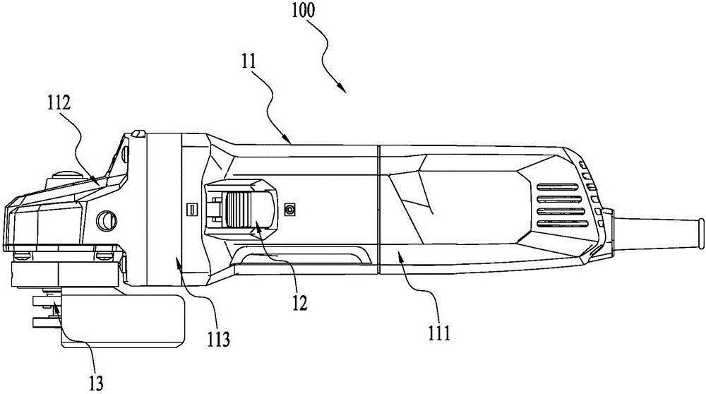
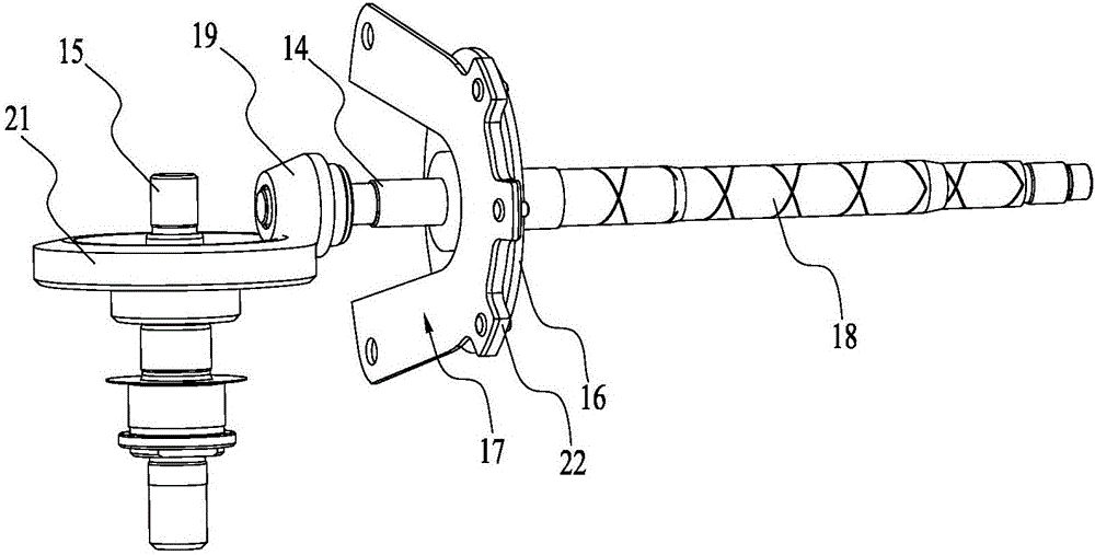
[0021] figure 1 The power tool 100 shown includes a housing 11, an operation switch 12, a prime mover (not shown in the figure), a transmission mechanism (not shown in the figure), and an output mechanism 13. Such as figure 2 As shown, the transmission mechanism includes at least the main shaft 14, the output mechanism 13 includes at least the output shaft 15, the main shaft 14 is provided with a brake disc 16, and the power tool 100 also includes a brake spring 17 in contact with the brake disc 16, so as to realize the control of the main shaft 14. move.

[0022] For the convenience of description, the power tool 100 takes an electric angle grinder as an example; of course, the power tool 100 can also be other hand-held grinding tools, such as a sander; or the power tool 100 can also be used to output torque, such as a screwdriver, Or a multi-function tool wi...


PUM


Abstract

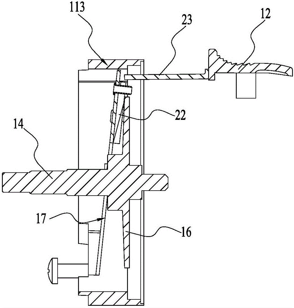
The invention discloses a power tool. The power tool comprises a shell, a main shaft and a braking elastic piece. The main shaft forms or is fixedly connected with a braking disc. The braking elastic piece is used for being in contact with the braking disc for braking the main shaft. The braking elastic piece comprises fixed portions and a movable portion. The fixed portions are fixedly connected to the shell. The movable portion can move relative to the shell. The movable portion is provided with a friction piece for being in contact with the braking disc. When the movable portion is in the first position, the friction piece is moved away from and not in contact with the braking disc; when the movable portion is in the second position, the friction piece is in contact with the braking disc; and the elastic bias movable portion of the braking elastic piece is moved to the second position from the first position. The braking elastic piece in the power tool is easy to assembly, and the occupied assembly space is small.

Description

Technical field [0001] The invention relates to a power tool, in particular to a power tool with a brake function. Background technique [0002] Grinding power tools such as angle grinders are generally equipped with a brake mechanism so that they can stop the rotation of functional accessories such as angle grinders in time after the user stops using them to protect the user's safety in use. [0003] Generally speaking, brakes are divided into electronic brakes and mechanical brakes. Electronic brakes have certain limitations and are easy to damage the motor, while mechanical brakes are direct and reliable. [0004] Existing mechanical brakes often use elastic elements to drive the brake pads to perform contact braking. However, in order to arrange the brake pads and the elastic elements at the same time and leave enough travel, power tools with mechanical brakes often assemble complicated and occupy mechanical space. Summary of the invention [0005] A power tool comprising: a hou...

Claims


Application Information

Patent Timeline
IPC IPC(8): B25F5/00
CPCB25F5/001
Inventor 张锐关向新
Owner NANJING CHERVON IND
Learn More