Eureka AIR delivers breakthrough ideas for toughest innovation challenges, trusted by R&D personnel around the world.

Electric bag composite dust collector

A technology of electric bag compounding and dust collector, which is applied in combination devices, chemical instruments and methods, separation methods, etc., can solve the problems of unsatisfactory dust removal effect, reduced service life of filter bag 1, short circuit of flue gas, etc.

Active Publication Date: 2018-12-14
FUJIAN LONGKING
View PDF5 Cites 2 Cited by
  • Summary
  • Abstract
  • Description
  • Claims
  • Application Information

AI Technical Summary

Problems solved by technology

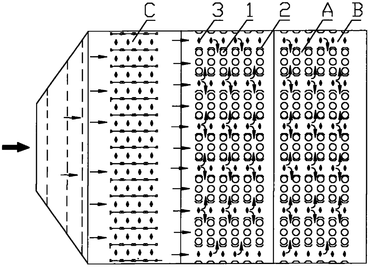
[0009] 1. In order to make full use of the space, establish an electric field channel, and protect the filter bag 1, the anode plate 2 and the filter bag 1 are very close, and the friction between the filter bag 1 and the anode plate 2 is prone to occur during operation, reducing the use of the filter bag 1 life;
[0010] two, figure 1 Among them, the filter bag row A includes three sets of three rows of filter bags 1, a considerable part of the flue gas will flow directly to the filter bag row A, that is, the electric field area between the filter bag row A is easy to form a short circuit of the flue gas during operation, The actual charging effect is poor, it cannot fully play its role, and the dust removal effect is not ideal

Method used


Image

  • Electric bag composite dust collector
  • Electric bag composite dust collector
  • Electric bag composite dust collector

Examples


Embodiment Construction

[0040] In order to enable those skilled in the art to better understand the technical solutions of the present invention, the present invention will be further described in detail below in conjunction with the accompanying drawings and specific embodiments.

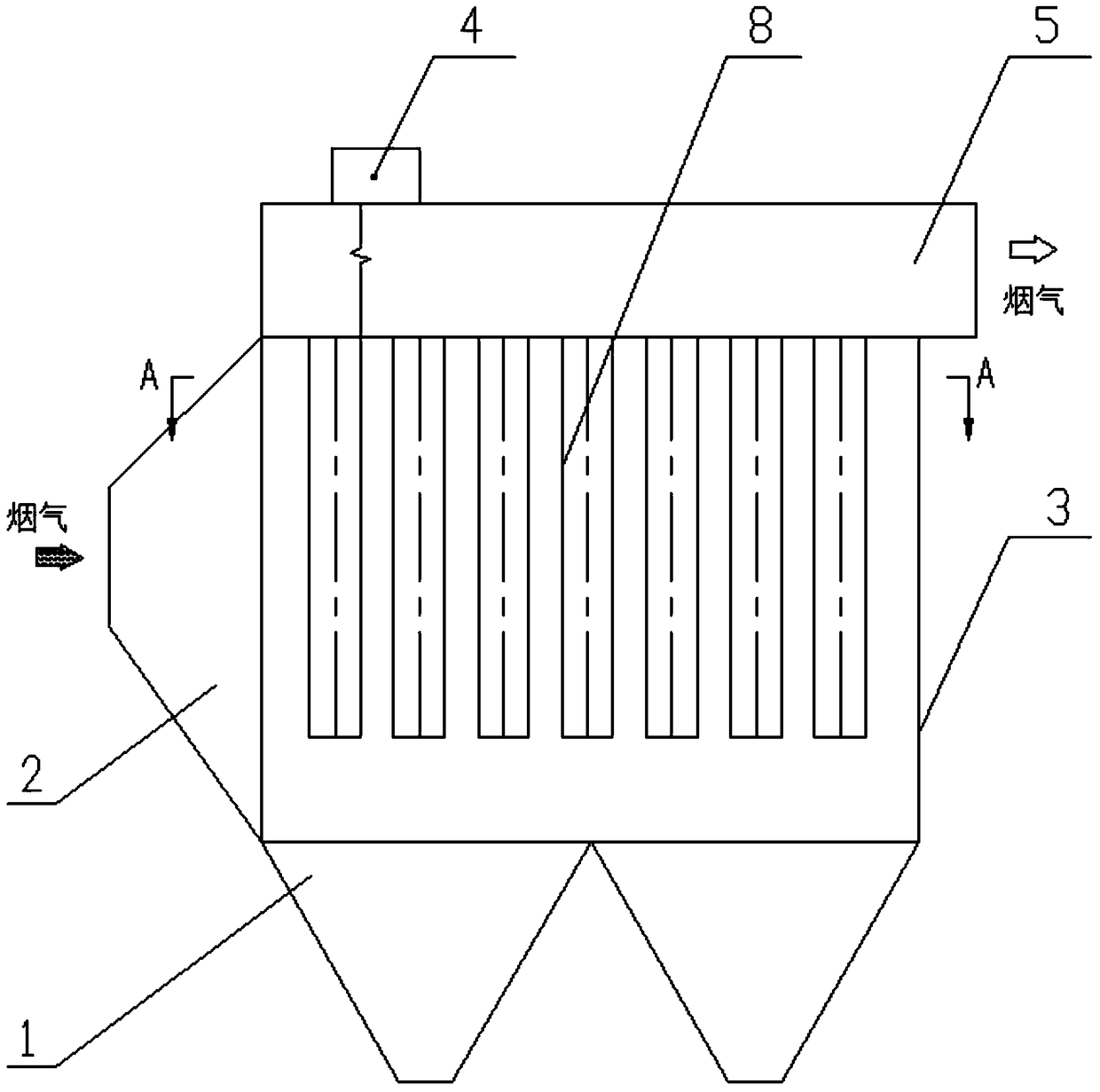
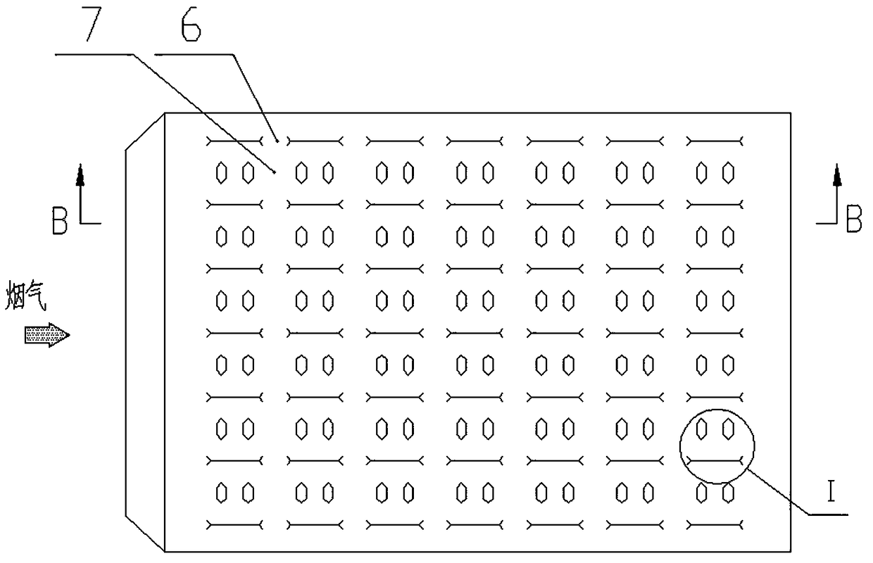
[0041] Please refer to figure 2 , figure 2 It is a structural schematic diagram of a specific embodiment of the electric bag composite dust collector provided by the present invention; image 3 for figure 2 The A-A direction diagram.

[0042] figure 2 The electrostatic bag composite dust collector shown in , includes an electric bag mixing area with a filter bag, that is, an area with both electric dust removal and bag dust removal functions. The flue gas enters the electric bag mixing area from the inlet horn 2, and the electric bag mixing area The collected dust falls into the ash hopper 1 at the bottom through the dust cleaning device, and the flue gas flows to the flue gas outlet 5 through the outlet of the fi...


PUM


Abstract

The invention discloses an electrostatic-bag composite dust collector which includes an electrostatic-bag mixing area provided with a filter bag and electric field. The filter bag is a metal filter bag. A negative discharge pole is arranged on the periphery of the metal filter bag. A positive pole plate is disposed in the electrostatic-bag mixing area and is corresponding to the negative discharge pole, so that the electric field is formed by the discharge pole and the positive pole plate. A negative pole system is formed by the metal filter bag, which is corresponding to the positive pole plate, so that friction on the filter bag is avoided in the technical scheme and service life of the filter bag is ensured. The electric field is formed by the metal filter bag and the discharge pole, so that charging property of dust is improved, and when the dust is captured by the filter bag, a loose dust layer is formed on the surface of filter bag due to the principle of like charge repelling each other, thereby preventing dust caking and improving dust removal efficiency. The metal filter bag is a negative pole system, so that under the constraint of electric field force, speed of the charged dust is reduced and the dust is remained in and even deposited in the electric field, while flue gas can flow towards the metal filter bag at high speed, so that the dust collector also can increase the air flowing speed in the filter bag area, thereby increasing utilization ratio of the filter bag and utilization ratio of space.

Description

technical field [0001] The invention relates to the technical field of dust collectors, in particular to an electric bag composite dust collector. Background technique [0002] Please refer to figure 1 , figure 1 It is a schematic structural diagram of a typical electric bag composite dust collector. [0003] The electric bag composite dust collector includes an electric dust removal area C and an electric bag mixing area, and the flue gas flows through the electric dust removal area C and the electric bag mixing area in sequence. The electric bag mixing area is formed by the filter bag row A and the electric field channel B arranged at intervals, wherein the filter bag row A includes at least one row of filter bags 1, the electric field channel B includes at least two anode plates 2, and the two anode plates 2 are provided There are discharge electrodes to form an electric field. The arrangement of the anode plates 2 is substantially parallel to the extension direction ...

Claims


Application Information

Patent Timeline
Patent Type & Authority Patents(China)
IPC IPC(8): B01D50/00
CPCB01D50/00
Inventor 黄晨晖陈东邱秉鑫钟海斌黄明锋
Owner FUJIAN LONGKING
Why Eureka
Eureka Blog
Learn More