Rotary pressure reducing valve

A pressure reducing valve and rotary technology, applied in the field of pressure reducing valves, can solve the problems of affecting downstream pressure regulation, unreliable sealing, easy damage to the sealing surface, etc., and achieve the effect of increasing service life

Active Publication Date: 2019-07-16
TIANJIN GUOWEI FEEDING & DRAINAGE EQUIP MENT MFG
View PDF5 Cites 0 Cited by
  • Summary
  • Abstract
  • Description
  • Claims
  • Application Information

AI Technical Summary

Problems solved by technology

Due to the structure moving up and down, it is easy to cause impurities to accumulate on the sealing surface, resulting in unreliable sealing, which in turn affects the adjustment of downstream pressure
In order to increase the sealing reliability of the sealing surface, the sealing surface is generally made of rubber or other soft materials, and the sealing surface is easily damaged after a period of time

Method used


Image

  • Rotary pressure reducing valve
  • Rotary pressure reducing valve
  • Rotary pressure reducing valve

Examples


Embodiment 1

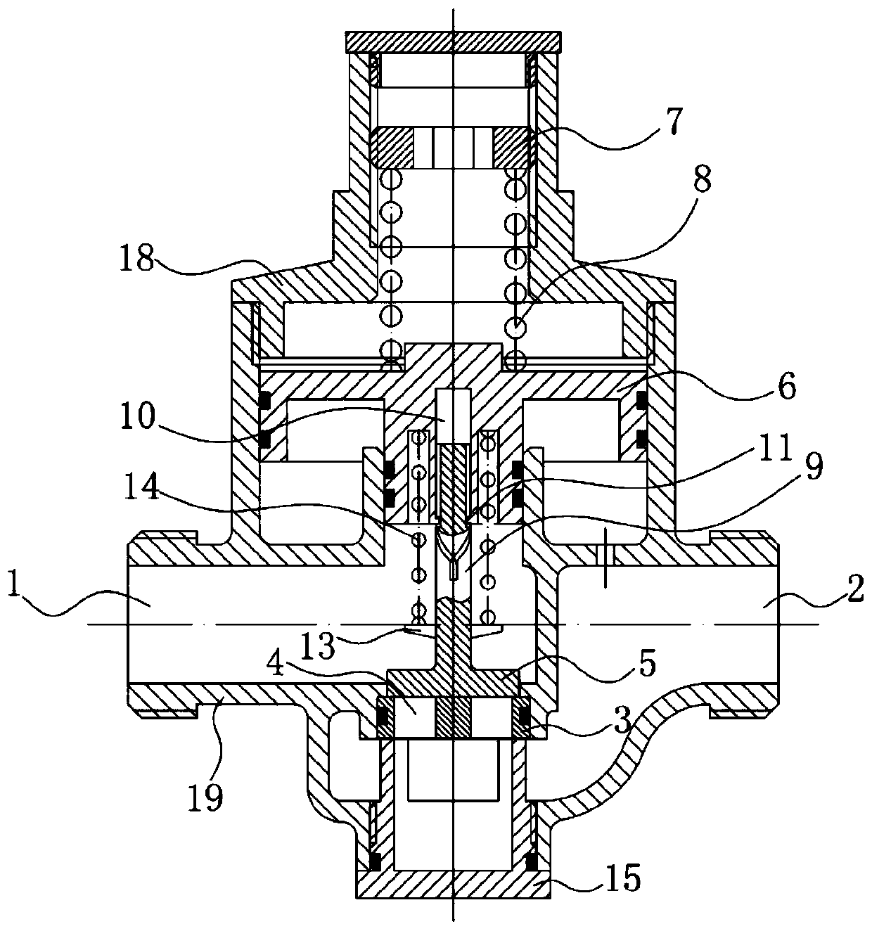
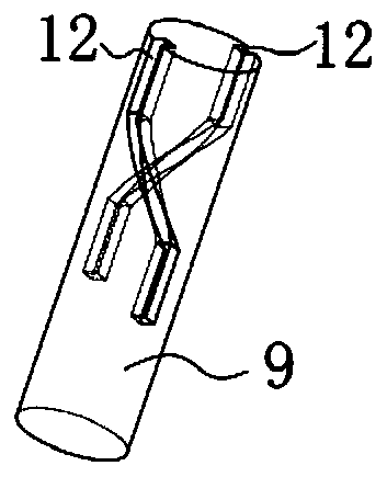
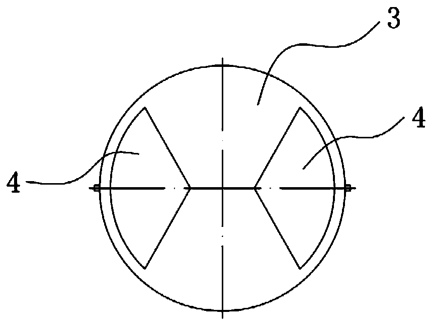
[0027] Such as figure 1 As shown, this embodiment proposes a rotary pressure reducing valve, including a pressure regulating assembly arranged between the inlet 1 and the outlet 2 of the pressure reducing valve, and a fixed seat 3 is arranged in the pressure reducing valve, between the inlet 1 and the outlet 2 Through the opening 4 on the fixed seat 3, the pressure adjustment component is connected with a reversing structure, and the reversing structure is connected with a rotary valve plate 5. The pressure change of the outlet 2 changes the position of the pressure regulating component, so that the reversing structure drives the rotary valve. When the plate 5 rotates, the rotary valve plate 5 cooperates with the fixed seat 3 , and the area of ​​the opening 4 can be changed during the rotation of the rotary valve plate 5 .

[0028] The rotary pressure reducing valve transforms the original method of changing the size of the flow channel area and stabilizing the pressure at the...

Embodiment 2

[0038] The difference between this embodiment and Embodiment 1 is: as Image 6 As shown, the direction changing structure is a crank connecting rod structure, including a connecting rod 16 and a crank 17. The connecting rod 16 is connected to the pressure regulating assembly, and the crank 17 is connected to the rotary valve plate 5. The length direction of the crank 17 and the length direction of the connecting rod 16 are Fitted at 90°.

[0039] The rotary pressure reducing valve changes the flow area through rotary motion. In addition to the structures of Embodiments 1 and 2, the gear and rack transmission mode, the multi-point connecting rod mode or the magnetic field mode can also be selected to realize the rotation of the rotary valve plate 5. According to Specific needs to be selected.


PUM


Abstract

The invention discloses a rotary pressure reducing valve, and relates to the technical field of pressure reducing valves. The rotary pressure reducing valve comprises a pressure adjusting module arranged between an inlet and an outlet of the pressure reducing valve; a fixed base is arranged in the pressure reducing valve; the inlet and the outlet are communicated through an opening in the fixed base; the pressure adjusting module is connected with a direction change structure; the direction change structure is connected with a rotating valve plate; the pressure change of the outlet enables the position of the pressure adjusting module to change, so that the direction change structure drives the rotating valve plate to rotate; the rotating valve plate is matched with the fixed base; and the area of the opening can be changed in the rotating process of the rotating valve plate. As the area of the opening is changed through controlling rotation of the rotating valve plate, the pressure of the outlet of the pressure reducing valve is balanced and stabilized; and a sealing surface in a rotating form is formed between the rotating valve plate and the fixed base, so that impurities are not easy to accumulate on the sealing surface, and can be autonomously removed, and the service life of the pressure reducing valve is prolonged.

Description

technical field [0001] The invention relates to the technical field of pressure reducing valves, in particular to a rotary pressure reducing valve. Background technique [0002] The pressure reducing valve is a valve that reduces the inlet pressure to a certain required outlet pressure through adjustment, and relies on the energy of the medium itself to keep the outlet pressure automatically stable. From the point of view of fluid mechanics, the pressure reducing valve is a throttling element whose local resistance can be changed, that is, by changing the throttling area, the flow velocity and the kinetic energy of the fluid are changed, resulting in different pressure losses, so as to achieve the purpose of decompression. [0003] The existing pressure reducing valves rely on the up and down movement of the valve plate to change the area of ​​the flow channel, thereby changing the downstream pressure and relying on the balance between the spring force and the downstream pre...

Claims


Application Information

Patent Timeline
Patent Type & Authority Patents(China)
IPC IPC(8): F16K17/30F16K3/08F16K3/10F16K3/314F16K31/122F16K31/126
CPCF16K3/08F16K3/10F16K3/314F16K17/30F16K31/1221F16K31/1264
Inventor 刘永龚高石刘庆王阳春
Owner TIANJIN GUOWEI FEEDING & DRAINAGE EQUIP MENT MFG
Why Eureka
Try Eureka