
A constant temperature and constant flow valve core with linked flow diversion function

A technology of constant flow valve and diverter valve, which is applied in the field of valve core, can solve problems such as the temperature of the outlet water is not adjusted high, and the temperature of the outlet water exceeds the standard range, so as to achieve the effect of improving the stability and reliability of the work

Active Publication Date: 2018-09-28
JOMOO KITCHEN & BATHROOM
View PDF6 Cites 0 Cited by
  • Summary
  • Abstract
  • Description
  • Claims
  • Application Information

AI Technical Summary

Problems solved by technology

[0002] Since the existing thermostatic valve core adjusts the water outlet problem by changing the ratio of cold water and hot water inlet, therefore, while adjusting the temperature, it will inevitably bring changes in the flow of hot water and cold water, so that the thermostatic valve core Under the condition that the temperature of the outlet water cannot be kept constant, the flow rate of the inlet water can be kept constant
[0003] In addition, during the use of the existing thermostatic spool, there will be a problem that the handwheel is adjusted to the hottest end, and the outlet water temperature cannot be adjusted to a high level. Moreover, the existing thermostatic spool may also cause the temperature of the outlet water to decrease when the pressure difference between cold and hot water is large. Questions beyond the scope of the standard

Method used


Image

  • A constant temperature and constant flow valve core with linked flow diversion function

Examples


Embodiment Construction

[0026] In order to make the technical problems, technical solutions and beneficial effects to be solved by the present invention clearer and clearer, the present invention will be further described in detail below in conjunction with the accompanying drawings and embodiments. It should be understood that the specific embodiments described here are only used to explain the present invention, not to limit the present invention.

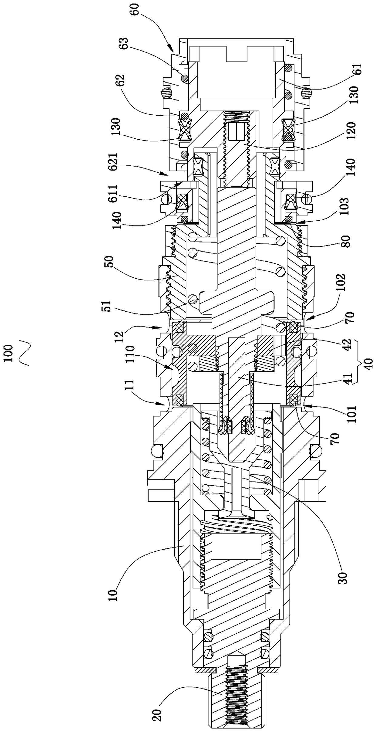
[0027] see figure 1 , is a schematic diagram of the structure of the constant temperature and constant flow valve core with linked flow diversion function provided by the embodiment of the present invention. The constant temperature and constant flow spool 100 with linked flow diversion function includes a spool housing 10 , a rotary adjustment valve stem 20 , a safety spring assembly 30 , a temperature-sensing piston assembly 40 , a spool base 50 and a flow distribution assembly 60 .

[0028] Wherein, the rotation adjustment valve stem 20 extends into...


PUM


Abstract

The invention discloses a constant-temperature and constant-flow valve element with a linkage dividing function. The constant-temperature and constant-flow valve element with the linkage dividing function comprises a valve element shell, a temperature-sensing piston assembly, a valve element base and a dividing assembly. The valve element shell, the valve element base and the dividing assembly are sequentially connected to form a mixed water channel inside. The temperature-sensing piston assembly is accommodated in the mixed water channel, and one end of the temperature-sensing piston assembly abuts against the dividing assembly. A cold water inlet gap is formed between the valve element shell and the temperature-sensing piston assembly. A hot water inlet gap is formed between the valve element base and the temperature-sensing piston assembly. A hot water dividing gap is formed between the dividing assembly and the valve element base. Hot water is divided into a first path of hot water at the hot water inlet gap and divided into a second path of hot water at the hot water dividing gap.

Description

technical field [0001] The invention relates to the field of spools, in particular to a constant temperature and constant flow spool with linked flow diversion function. Background technique [0002] Since the existing thermostatic valve core adjusts the water outlet problem by changing the ratio of cold water and hot water inlet, therefore, while adjusting the temperature, it will inevitably bring changes in the flow of hot water and cold water, so that the thermostatic valve core Under the condition that the temperature of the outlet water cannot be kept constant, the flow rate of the inlet water is kept constant. [0003] In addition, during the use of the existing thermostatic spool, there will be a problem that the handwheel is adjusted to the hottest end, and the outlet water temperature cannot be adjusted to a high level. Moreover, the existing thermostatic spool may also cause the temperature of the outlet water to decrease when the pressure difference between cold a...

Claims


Application Information

Patent Timeline
Patent Type & Authority Patents(China)
IPC IPC(8): F16K11/02F16K31/64
CPCF16K11/02F16K31/002
Inventor 林孝发林孝山梁绍团陈名豪黄鲲鹏
Owner JOMOO KITCHEN & BATHROOM
Learn More