Anilox roller transmission mechanism of printing machine

A technology of transmission mechanism and anilox roller, which is applied in the direction of printing machines, general parts of printing machinery, printing, etc., can solve the problems that the double-sided printing on the front of the substrate cannot be applied, and achieve the effect of highlighting the substantive characteristics

Active Publication Date: 2017-03-29
ZHEJIANG WEIGANG TECH CO LTD
View PDF6 Cites 4 Cited by
  • Summary
  • Abstract
  • Description
  • Claims
  • Application Information

AI Technical Summary

Problems solved by technology

When the anilox roller ink transfer and ink distribution do not affect each other, the anilox roller rotates in the forward direction, that is, the anilox roller rotates in one direction during printing, and it is not suitable for double-sided printing on the front of the substrate. The anilox roller needs to rotate in the forward direction, and when printing on the reverse side, the anilox roller needs to rotate in the reverse direction

Method used


Image

  • Anilox roller transmission mechanism of printing machine
  • Anilox roller transmission mechanism of printing machine

Examples


Embodiment Construction

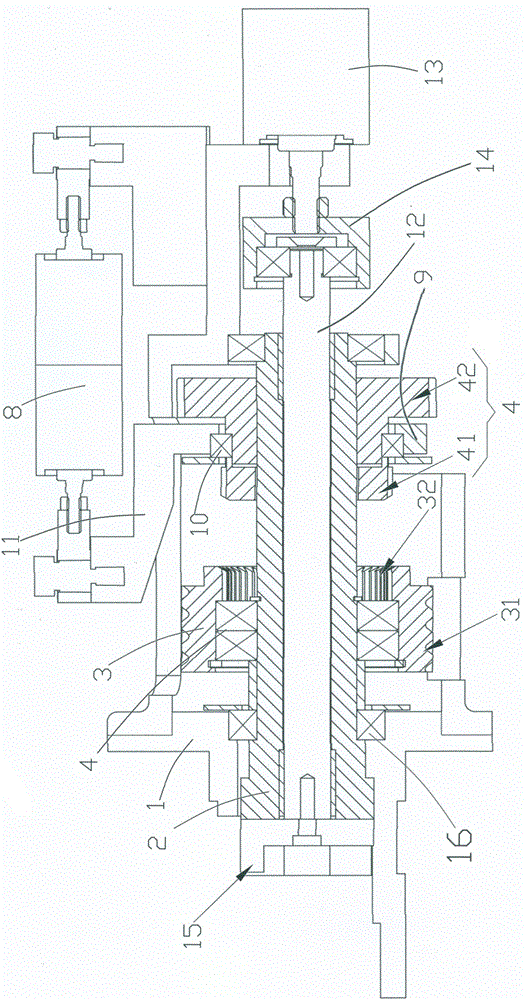
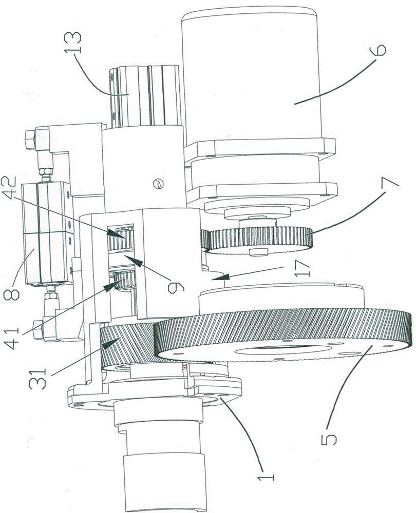
[0022] Referring to the accompanying drawings, the anilox roller transmission mechanism of the printing machine in this embodiment includes a mounting seat 1 and a transmission shaft 2 . The transmission shaft 2 is connected to the transmission of the anilox roller, and the transmission shaft 2 can drive the anilox roller to rotate.

[0023] Transmission shaft 2 is provided with positive and negative two-way rotation on mounting seat 1, and bidirectional rotating bearing 16 (adopting rolling bearing) can be set between transmission shaft 2 and mounting seat 1, so that rotate smoothly.

[0024] The transmission shaft 2 is connected with the first gear assembly 3 and the second gear assembly 4 .

[0025] The first gear assembly 3 has a first tooth portion 31 and a second tooth portion 32 . In this embodiment, as a preference, the first tooth portion 31 of the first gear assembly 3 is an outer ring gear, the second tooth portion 32 is an inner ring gear, and the first gear assem...


PUM


Abstract

The invention provides an anilox roller transmission mechanism of a printing machine. A transmission shaft of the anilox roller transmission mechanism rotates in two ways and is connected with a first gear assembly and a second gear assembly. The axial positions of the transmission shaft and the first gear assembly are kept unchanged. First tooth parts of the first gear assembly are in transmission fit with a first input gear. A first transmission device is in transmission with the first input gear. The second gear assembly comprises third tooth parts and fourth tooth parts. The second gear assembly moves in the axial direction relative to the transmission shaft. The second gear assembly and the transmission shaft synchronously rotate. A second transmission device is in transmission connection with a second input gear. The second gear assembly moves in the axial direction. Three-station switching is achieved when the fourth tooth parts are engaged with the second input gear, when the third tooth parts are engaged with the second tooth parts and when the fourth tooth parts are not engaged with the second input gear and the third tooth parts are not engaged with the second tooth parts. During printing, an anilox roller rotates forwards or backwards through transmission of the first transmission device, two-way rotation is achieved, and printing of the front face or the back face of a printed material is satisfied through printing ink transfer. When printing is not conducted, the anilox roller rotates through transmission of the second transmission device so as to conduct ink distribution. Printing ink transfer and ink distribution do not influence each other.

Description

technical field [0001] The invention relates to an anilox roller transmission mechanism of a printing machine. Background technique [0002] In a printing machine (such as a flexographic printing press), the ink is transferred to the plate roller through the anilox roller, and the plate roller cooperates with the bottom roller for printing. During printing, the plate roller is driven by a power source (such as a servo motor) to rotate to realize ink transfer; when not printing (such as interval time), the anilox roller is driven by another power source (such as an ordinary motor). Rotate to achieve ink distribution. The rotation of the anilox roller during ink transfer and ink distribution does not affect each other, the rotation speed is relatively high during ink transfer, and the rotation speed is relatively small during ink distribution, and is controlled by two power sources. When the anilox roller ink transfer and ink distribution do not affect each other, the anilox...

Claims


Application Information

Patent Timeline
Patent Type & Authority Applications(China)
IPC IPC(8): B41F31/13B41F31/10
CPCB41F31/10B41F31/13
Inventor 周炳松陈庆桃车文春於金华
Owner ZHEJIANG WEIGANG TECH CO LTD
Why Eureka
Try Eureka