


Quick Research
Generate reliable direction feasibility study reports for your R&D in just a few steps.

Technical Q&A
Discover and master advanced knowledge NOW. Basics, ideas, possibilities, all at once.

Find Solutions
As an expert in R&D theories, this can generate solutions to your technical problems instantly.

Evaluate Feasibility
Analyze your overall solution with one click, know your potential R&D risks in advance.

Monitor Landscape
Get weekly tech updates, stay abreast of the latest tech innovations and key insights.
Arc extinguish chamber assembling tool
A technology for assembling tooling and arc-extinguishing chambers, applied in the direction of manufacturing tools, workpiece clamping devices, etc., can solve the problems of high labor intensity and low assembly efficiency, and achieve the effects of low labor intensity, high assembly efficiency and convenient operation.
- Summary
- Abstract
- Description
- Claims
- Application Information
AI Technical Summary
Problems solved by technology
Method used
Image


Examples
Embodiment 1
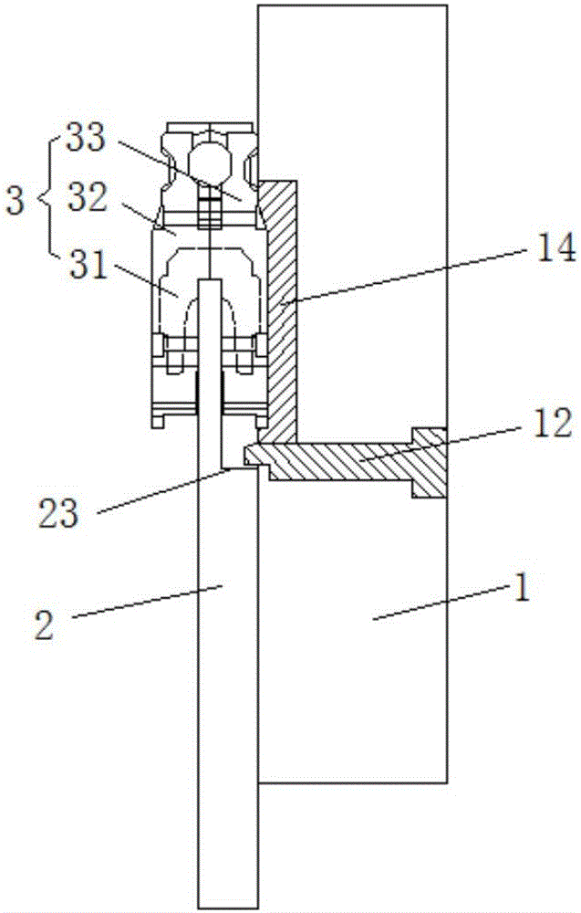
[0024] Embodiment one: if figure 1 and figure 2 As shown, a tool for assembling an arc extinguishing chamber includes a bottom plate 1 and an arc extinguishing blade positioning plate 2 . The arc extinguisher positioning plate 2 is a plate-like structure placed horizontally. There is a long strip-shaped and inclined guide hole 21 in the middle of the arc extinguisher positioning plate 2. There are several card slots 22 at the front end of the arc extinguisher positioning plate 2. The front end Limiting steps 23 are provided below. The width of each slot 22 and the arrangement of the slots 22 correspond to the arc extinguishing plates 31 in the arc extinguishing chamber 3 one by one. The center of the bottom plate 1 is provided with an arc extinguishing chamber assembly area 11 , and four corners are provided with fixing holes 15 . The arc extinguishing chamber assembly area 11 is provided with a positioning mechanism for limiting the movement of the left arc extinguishing ...
Embodiment 2
[0025] Embodiment two: if Figure 3-5 As shown, a tool for assembling an arc extinguishing chamber includes a bottom plate 6 and an arc extinguishing blade positioning plate 7 . The arc extinguishing plate positioning plate 7 is a plate-shaped structure placed horizontally, and the arc extinguishing plate positioning plate 7 is provided with a long strip-shaped and inclined guide hole 71 in the middle. A limit step 73 is provided below. The width of each locking slot 72 and the arrangement of the locking slots 72 correspond to the arc extinguishing plates in the arc extinguishing chamber one by one. The center of the bottom plate 6 is provided with an arc extinguishing chamber assembly area 61 , and four corners of the bottom plate are provided with fixing holes 64 . The arc extinguishing chamber assembly area 61 is a rectangular cavity capable of accommodating the left or right arc extinguishing hood 8. The left and right ends and the front end of the arc extinguishing cham...
PUM
 Abstract
Description
Claims
Application Information
 - R&D Engineer
- R&D Manager
- IP Professional
- Industry Leading Data Capabilities
- Powerful AI technology
- Patent DNA Extraction
Browse by: Latest US Patents, China's latest patents, Technical Efficacy Thesaurus, Application Domain, Technology Topic, Popular Technical Reports.
© 2024 PatSnap. All rights reserved.Legal|Privacy policy|Modern Slavery Act Transparency Statement|Sitemap|About US| Contact US: help@patsnap.com