Stator and casing stamping tool

A stator casing and tooling technology, which is applied in the direction of electromechanical devices, manufacturing motor generators, electrical components, etc., can solve the problems of unguaranteed installation quality, high installation difficulty, and low installation efficiency, so as to reduce the difficulty and improve the installation efficiency. Efficiency, the effect of guaranteeing product quality

Pending Publication Date: 2017-03-22
鹤山市源创电机有限公司
View PDF5 Cites 1 Cited by
  • Summary
  • Abstract
  • Description
  • Claims
  • Application Information

AI Technical Summary

Problems solved by technology

[0002] At present, the assembly of the stators of some small motors and the casings set on their periphery is completed by ordinary stamping equipment and corresponding tooling. The stamping tooling generally includes a base for fixing the casing and a pressure plate for contacting the stamping equipment. Since the casing and the stator are initially fixed manually and then put into the tooling for stamping, if the initially fixed stator and the machine If the casing is relatively inclined, the coaxiality between the stamped stator and the casing will also deviate, and the installation quality cannot be guaranteed. Therefore, it is necessary to artificially coincide the axis of the stator and the casing during the initial fixation, which is difficult to install and efficient. Low

Method used


Image

  • Stator and casing stamping tool
  • Stator and casing stamping tool

Examples


Embodiment Construction

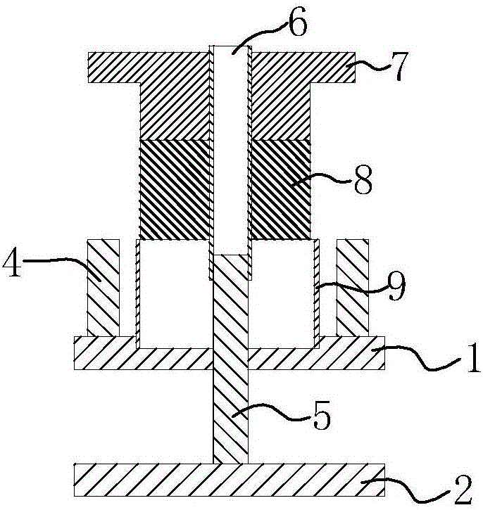
[0015] refer to Figure 1 to Figure 2 , a stamping tool for a stator casing of the present invention includes a base for placing a casing 9, the base includes an upper chassis 1 and a lower chassis 2 arranged parallel to the upper chassis 1, the upper chassis 1 and the lower chassis 2 They are connected by several connecting columns 3. The upper chassis 1 is in the shape of a ring, and the ring shape includes an inner circle, an outer circle and a ring part between the two. The inner circle is provided for positioning the casing 9 steps, the ring portion is provided with a number of top columns 4, the center of the lower chassis 2 is vertically provided with a centering column 5, and the punching tooling also includes a centering sleeve 6 and a centering sleeve 6 that cooperate with the centering column 5 The pressure plate 7 is vertically arranged with the centering sleeve 6, and the top column 4 restricts the pressure plate 7 to move up and down. During installation, the st...


PUM


Abstract

The invention discloses a stator and casing stamping tool, which comprises a base for placing a casing, wherein the base comprises an upper base plate, a lower base plate, a centering sleeve matched with a centering post and a pressure plate; the lower base plate is arranged in parallel to the upper base plate; the upper base plate is connected with the lower base plate through a plurality of connecting posts; the upper base plate is in a circular shape; the circular shape comprises an inner circle, an outer circle and a circular part between the inner circle and the outer circle; the inner circle is provided with a step for locating the casing; the circular part is provided with a plurality of top posts; the center of the lower base plate is vertically provided with the centering post; the pressure plate is arranged vertically to the centering sleeve; and the top posts limit up-and-down action of the pressure plate. According to the stator and casing stamping tool, the preliminary fixing difficulty is reduced through coordination of the centering post and the centering sleeve and arrangement of the structures of the pressure plate sleeving the outside of the centering sleeve and the like; the installation efficiency is improved; the stator and casing stamping tool can meet the coaxiality requirement of a stator and the casing and the quality of a product is ensured.

Description

technical field [0001] The invention relates to a punching tool for a stator casing. Background technique [0002] At present, the assembly of the stators of some small motors and the casings set on their periphery is completed by ordinary stamping equipment and corresponding tooling. The stamping tooling generally includes a base for fixing the casing and a pressure plate for contacting the stamping equipment. Since the casing and the stator are initially fixed manually and then put into the tooling for stamping, if the initially fixed stator and the machine If the casing is relatively inclined, the coaxiality between the stamped stator and the casing will also deviate, and the installation quality cannot be guaranteed. Therefore, it is necessary to artificially coincide the axis of the stator and the casing during the initial fixation, which is difficult to install and efficient. Low. Contents of the invention [0003] The present invention aims to solve the technical ...

Claims


Application Information

Patent Timeline
Patent Type & Authority Applications(China)
IPC IPC(8): H02K15/14
CPCH02K15/14
Inventor 麦启源
Owner 鹤山市源创电机有限公司
Why Eureka
Try Eureka