Cable branch box capable of remote monitoring and control

A cable branch box, remote monitoring technology, applied in the direction of electrical components, substation/switch layout details, substation/switchgear cooling/ventilation, etc., can solve the problem of labor and material resources for search and maintenance, failure to realize distribution network automation, branch Problems such as low box life, to protect the stability and performance of use, prevent aging, and improve reliability

Inactive Publication Date: 2017-03-22
河北郎尊电力科技有限公司
View PDF14 Cites 5 Cited by
  • Summary
  • Abstract
  • Description
  • Claims
  • Application Information

AI Technical Summary

Problems solved by technology

[0002] The cable branch box is a device used as a cable branch. The main function of the cable branch box is to branch or transfer the cables. It mainly plays the role of cable branching and cable switching; on a relatively long line, the length of the cable cannot To meet the requirements of the line, you must use cable connectors or cable transfer boxes. Usually, cable intermediate connectors are used for short distances. In order to ensure safety, the cable branch box will be considered for switching; so the cable branch box is widely used outdoors. With the advancement of technology, the number of cable branch boxes with switches is also increasing, and urban cables often use double Loop power supply mode, so some people directly call the branch box with switch as outdoor ring network cabinet, but most of such ring network cabinets cannot realize distribution network automation at present, and various faults are caused by moisture inside the branch box. Maintenance requires manpower and material resources, and such branch boxes generally have problems such as low service life and frequent failures

Method used


Image

  • Cable branch box capable of remote monitoring and control
  • Cable branch box capable of remote monitoring and control
  • Cable branch box capable of remote monitoring and control

Examples


Embodiment Construction

[0030] Below in conjunction with accompanying drawing and embodiment, further elaborate the present invention. In the following detailed description, certain exemplary embodiments of the invention are described by way of illustration only. Needless to say, those skilled in the art would realize that the described embodiments can be modified in various different ways, all without departing from the spirit and scope of the present invention. Accordingly, the drawings and description are illustrative in nature and not intended to limit the scope of the claims.

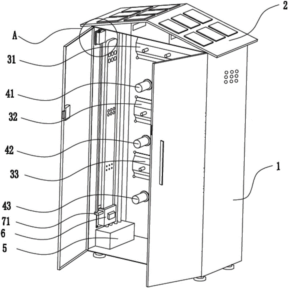
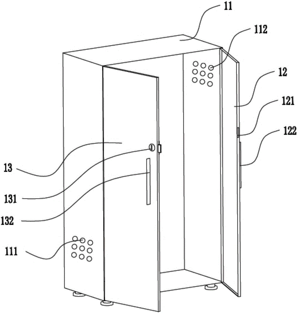
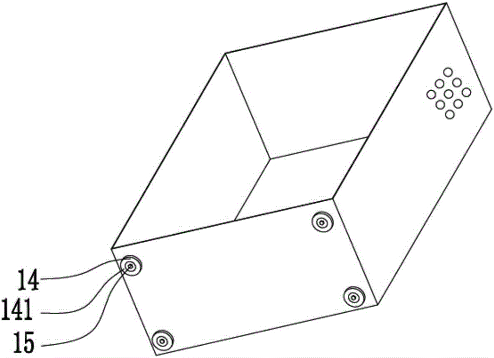
[0031] Such as Figure 1 to Figure 8As shown, the cable branch box that can be remotely monitored according to this embodiment includes a box body 1, a storage board, a battery 5, a cooling assembly 6 and a control assembly 7, the box body 1 includes a box body 11, and the front side of the box body 11 Openings are provided and the left door body 13 and the right door body 12 are respectively connected by hinges. The lo...


PUM


Abstract

The invention discloses a cable branch box capable of remote monitoring and control. The box comprises a box body, wherein a storage plate is arranged in the box body and comprises a first horizontal substrate, a second horizontal substrate and a third horizontal substrate, the first horizontal substrate and the third horizontal substrate and the third horizontal substrate and the second horizontal substrate are connected respectively by a first inclined plate and a second inclined plate, a plurality of projection welding studs are arranged on the third horizontal substrate and are used for fixing electronic components, a cooling assembly comprises a cooing assembly air duct and a motor box which are sequentially arranged from top to bottom, the cooling assembly air duct is in a hollow cuboid, the motor box is arranged in corresponding to an air inlet, the motor drives an air guide wheel, a control module is connected with the cooling assembly through a connection wire and is provided with a temperature sensor and a wireless signal emitter, and the temperature sensor is used for detecting a temperature in the box. By the cable branch box, remote control can be achieved, an abnormal condition is effectively prevented, and the reliability is improved. The box is suitably and widely used in the cable branch box.

Description

technical field [0001] The invention relates to the technical field of electric equipment, in particular to a cable branch box capable of remote monitoring. Background technique [0002] The cable branch box is a device used as a cable branch. The main function of the cable branch box is to branch or transfer the cables. It mainly plays the role of cable branching and cable switching; on a relatively long line, the length of the cable cannot To meet the requirements of the line, you must use cable connectors or cable transfer boxes. Usually, cable intermediate connectors are used for short distances. In order to ensure safety, the cable branch box will be considered for switching; so the cable branch box is widely used outdoors. With the advancement of technology, the number of cable branch boxes with switches is also increasing, and urban cables often use double Loop power supply mode, so some people directly call the branch box with switch as outdoor ring network cabinet,...

Claims


Application Information

Patent Timeline
Patent Type & Authority Applications(China)
IPC IPC(8): H02G3/08H02B1/56H02B1/46
CPCH02G3/08H02B1/46H02B1/565
Inventor 尚士辉张战旗
Owner 河北郎尊电力科技有限公司
Why Eureka
Try Eureka