USB Type-C adapter and implementation method thereof
An implementation method and adapter technology, applied in the direction of connection, parts and electrical components of the connection device, etc., can solve the problems of incompatible audio signal transmission and the like
- Summary
- Abstract
- Description
- Claims
- Application Information
AI Technical Summary
Problems solved by technology
Method used
Image
Examples
Embodiment 1
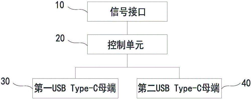
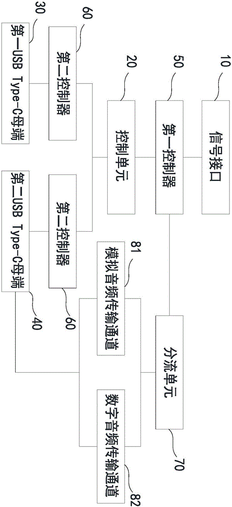
[0034] Such as figure 1 , 2 As shown, a USB Type-C adapter includes: a signal interface 10 , two USB Type-C female terminals, and a control unit 20 .
[0035] Specifically, the signal interface 10 is used to transmit signals including audio signals and charging signals. The signal interface 10 may be a USB Type-C signal interface.
[0036] Two USB Type-C receptacles, respectively defined as a first USB Type-C receptacle 30 and a second USB Type-C receptacle 40 , are respectively connected to the signal interface 10 . The first USB Type-C female end 30 is used to transmit charging signals, and the second USB Type-C female end 40 is used to transmit audio signals.
[0037] The control unit 20 is respectively connected between the signal interface 10 and the first USB Type-C female end 30, and between the signal interface 10 and the second USB Type-C female end 40, the control unit 20 is used to identify the type of the signal, and Different types of signals are transmitted t...
Embodiment 2
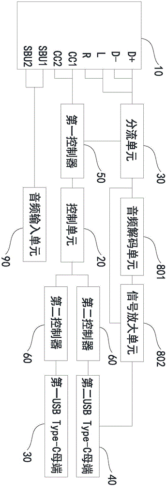
[0052] Compared with the USB Type-C adapter in Embodiment 1, such as image 3 As shown, the signals of the two USB Type-C female terminals in the second embodiment, that is, the first USB Type-C female terminal 30 and the second USB Type-C female terminal 40 can realize intelligent switching.
[0053] The control unit 20 is respectively connected between the signal interface 10 and the first USB Type-C female end 30, and between the signal interface 10 and the second USB Type-C female end 40. The control unit 20 is used to identify the type of the signal and differentiate Types of signals are transmitted to different USB Type-C receptacles respectively. Specifically, when the first USB Type-C receptacle 30 is connected to an external device, and the control unit 20 recognizes that the signal transmitted by the external device is a charging signal, it transmits the charging signal to the first USB Type-C receptacle 30 . Specifically, it intelligently recognizes the function of...
Embodiment 3
[0059] This case also provides an implementation method of a USB Type-C adapter, such as Figure 4 shown, including:
[0060] S1: using a signal interface to transmit signals including audio signals and charging signals;
[0061] S2: using two USB Type-C female ports to transmit the signal;
[0062] S3: Using a control unit 20 to identify whether the signal transmitted by a USB Type-C female end is an audio signal;
[0063] S4: If yes, transmit the audio signal to the USB Type-C female end; the other USB Type-C female end is fixedly used for charging signal transmission;
[0064] S5: If not, transmit the charging signal to the USB Type-C female end; the other USB Type-C female end is fixedly used for audio signal transmission.
PUM
 Abstract
Description
Claims
Application Information
 - R&D Engineer
- R&D Manager
- IP Professional
- Industry Leading Data Capabilities
- Powerful AI technology
- Patent DNA Extraction
Browse by: Latest US Patents, China's latest patents, Technical Efficacy Thesaurus, Application Domain, Technology Topic, Popular Technical Reports.
© 2024 PatSnap. All rights reserved.Legal|Privacy policy|Modern Slavery Act Transparency Statement|Sitemap|About US| Contact US: help@patsnap.com


