
A Design Method for Row Spacing Between Pressure Relief Boreholes

A design method and support pressure technology, applied in calculation, instrumentation, geometric CAD, etc., can solve the problems of increasing the amount of drilling engineering, unfavorable coal and rock mass stability, and the lack of pressure relief effect of row spacing

Active Publication Date: 2019-06-21
HENAN POLYTECHNIC UNIV
View PDF5 Cites 0 Cited by
  • Summary
  • Abstract
  • Description
  • Claims
  • Application Information

AI Technical Summary

Problems solved by technology

At present, the empirical analogy method and empirical formula method are mainly used to determine the row spacing between pressure relief boreholes. If the spacing is too large, the pressure relief effect will not be achieved, and if the row spacing is too small, it will not be conducive to maintaining the stability of the coal and rock mass, and will increase the amount of drilling work. It is of great significance to exert the pressure relief effect of drilling

Method used


Image

  • A Design Method for Row Spacing Between Pressure Relief Boreholes
  • A Design Method for Row Spacing Between Pressure Relief Boreholes
  • A Design Method for Row Spacing Between Pressure Relief Boreholes

Examples


Embodiment Construction

[0031] refer to Figure 1~6 The present invention is described, a method for designing the row spacing between pressure relief boreholes, the method is divided into three steps:

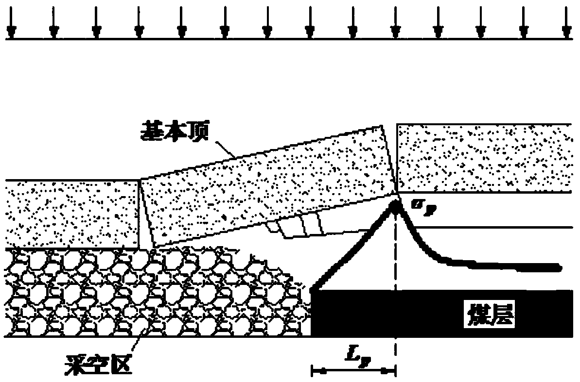
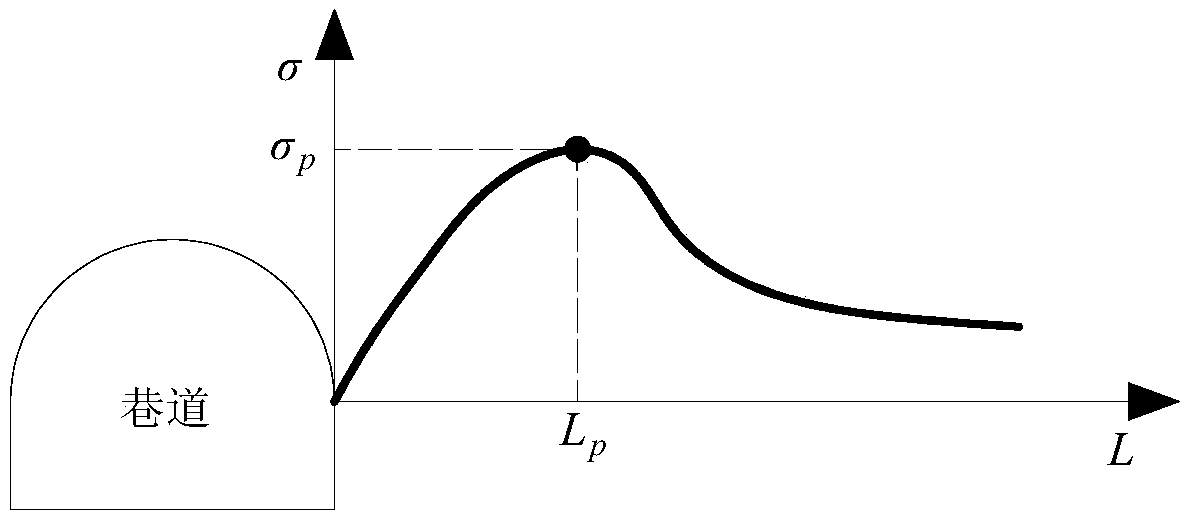
[0032] (S1) The application site of pressure relief drilling in coal mines is generally located in the working face, roadway and its adjacent positions. Before designing the row spacing between pressure relief drilling holes, it is first necessary to evaluate the stress environment at the pressure relief site and calculate the supporting pressure of the surrounding rock of the working face or roadway Peak σ p and its position L p . For the peak bearing pressure σ of the surrounding rock of the working face p and its position L p The calculation method is shown in formulas (1) and (2), according to the working face mining height m, side pressure coefficient A, coal internal friction angle Coal internal cohesion c, stress concentration coefficient k, average body force γ of overlying strata, buri...


PUM


Abstract

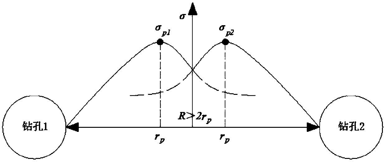
The invention relates to a design method for row space between pressure relief boreholes. The method comprises the following three steps of: before the row space between the pressure relief boreholes is designed, firstly, requiring to evaluate the stress environment of a pressure relief site, and calculating a working face (roadway) surrounding rock supporting pressure peak value [Sigma]p and a peak value position Lp; selecting a surrounding rock on the Lp as an analysis object, adopting a corrected surrounding rock elastoplasticity analytical solution to calculate a borehole plastic zone radius rp, taking the rp as an index for evaluating the single-hole action range of the borehole, and determining the maximum row space between the boreholes as R which is less than or equal to 2rp; and meanwhile, adopting the elastoplasticity analytical solution to calculate the evolution curve of the circumferential stress [Sigma][Theta] of the borehole, taking the stress of a crosspoint of the circumferential stress curves of the adjacent boreholes as [Sigma]m, taking the stress [Sigma]0 of primary rock of an experiment site as an evaluation index, and determining the condition of the minimum row space R between the boreholes as [Sigma]m which is greater than or equal to [Sigma]0. The method is simple in operation and high in practicality and can be applied to fields including high-stress roadway pressure relief, rock burst prevention and treatment, high gassy seam permeability increasing and the like, the design accuracy of the row space between the boreholes can be effectively improved, and a borehole engineering quantity is lowered.

Description

technical field [0001] The invention belongs to the field of coal mining, and relates to a design method for the row spacing between pressure-relieving boreholes, which can be extended and applied to the fields of pressure-relieving in high-stress roadways, prevention and control of rock burst, anti-permeability enhancement in high-gas coal seams, and the like. Background technique [0002] At present, drilling pressure relief technology is mainly used in projects such as rock burst prevention, high-gas coal seam permeability enhancement, and high-stress roadway stress. Although the functions in various projects are not the same, there is a large similarity in principle . For example, the prevention and control of rock burst is mainly through the artificial construction of large-diameter pressure-relief drilling holes in the coal rock layer, using the deformation and destruction of the drilling holes to release the elastic deformation properties accumulated inside the coal r...

Claims


Application Information

Patent Timeline
Patent Type & Authority Patents(China)
IPC IPC(8): G06F17/50
CPCG06F30/17
Inventor 王猛王襄禹肖同强褚廷湘石亚康刘恩来
Owner HENAN POLYTECHNIC UNIV
Learn More