
An automatic capping machine and its working method

A capping machine, automatic technology, applied in the direction of threaded bottle caps, etc., can solve the problems of over-tightening, slow capping speed, and untightened bottle caps, etc., to achieve the effect of convenient operation, easy clamping, and convenient control

Active Publication Date: 2018-08-28
CHANGZHOU TONY PACK WEIGHING SYST CO LTD
View PDF6 Cites 0 Cited by
  • Summary
  • Abstract
  • Description
  • Claims
  • Application Information

AI Technical Summary

Problems solved by technology

[0002] Capping machine, also known as capping machine, capping machine or cap locking machine, is used for cap screwing and loosening equipment after plastic bottles and glass bottles are packaged. It is one of the main equipments of automatic filling production line. Some capping machines are equipped with a device for tightening the bottle cap, which tends to slide relative to the bottle cap during use, resulting in the phenomenon that the bottle cap is not tightened tightly and the positioning is inaccurate. And it is impossible to accurately control the capping force, resulting in either not tightening, or too tight, at the same time labor-intensive, slow capping speed, low work efficiency, complex structure, not conducive to maintenance

Method used


Image

  • An automatic capping machine and its working method
  • An automatic capping machine and its working method
  • An automatic capping machine and its working method

Examples


Embodiment 1

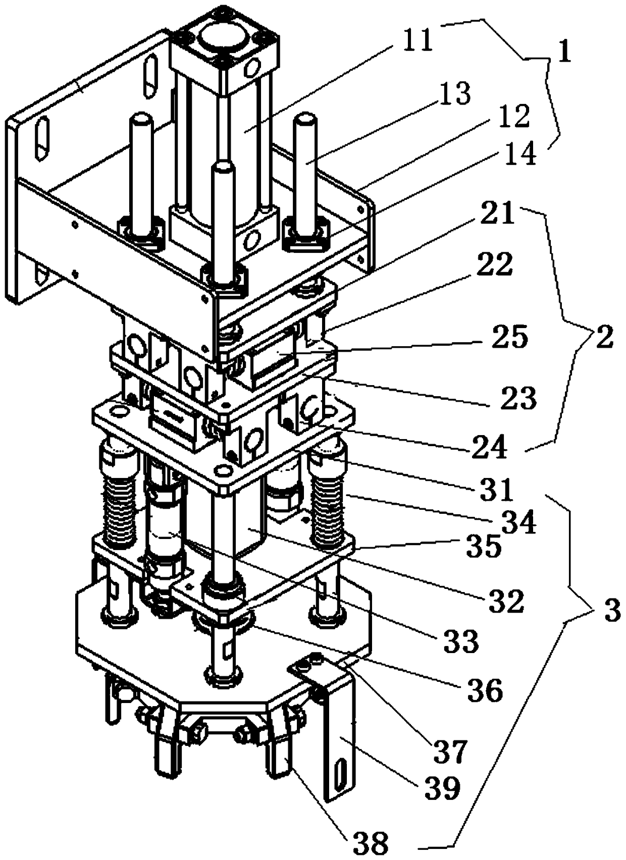
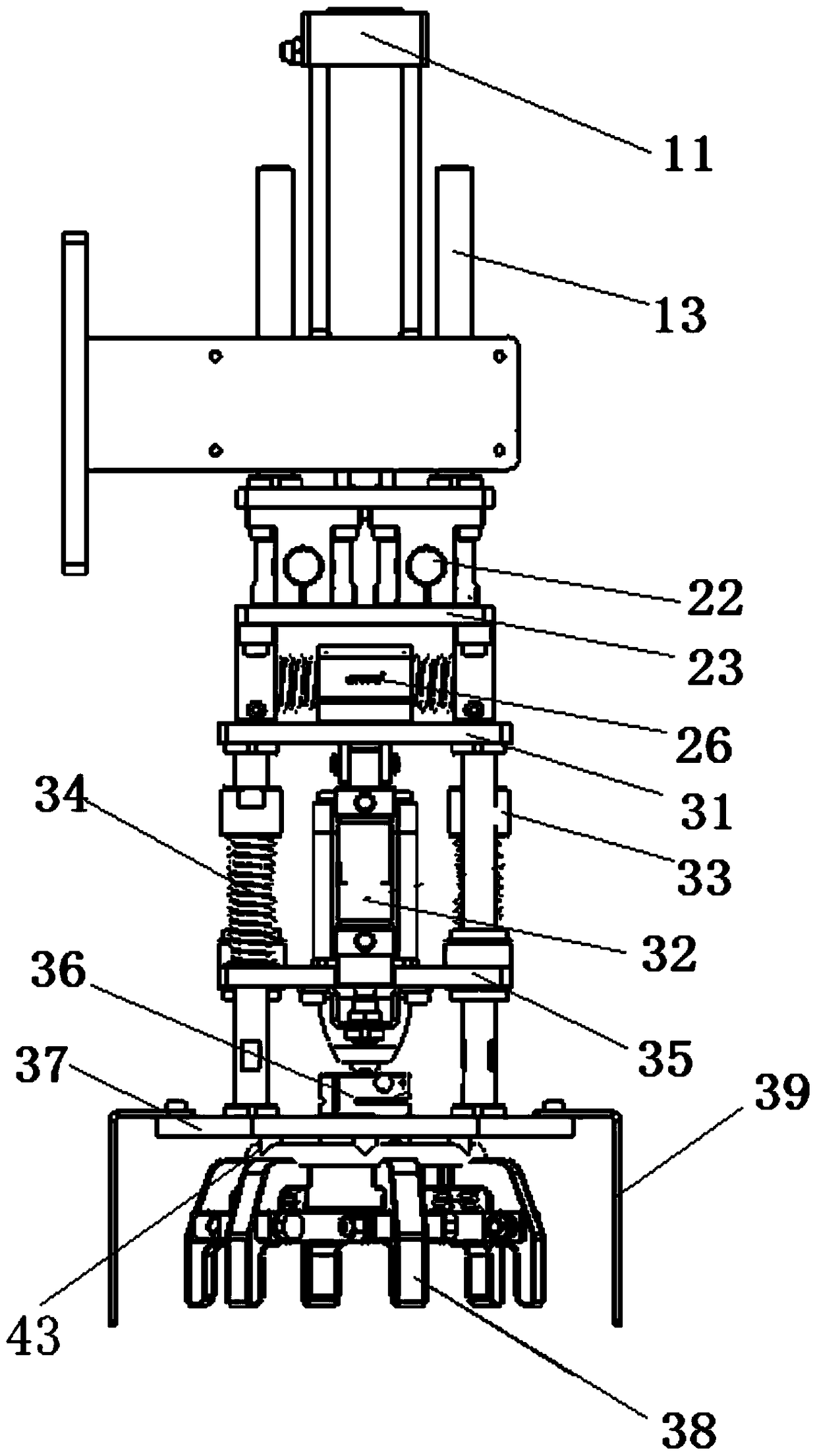
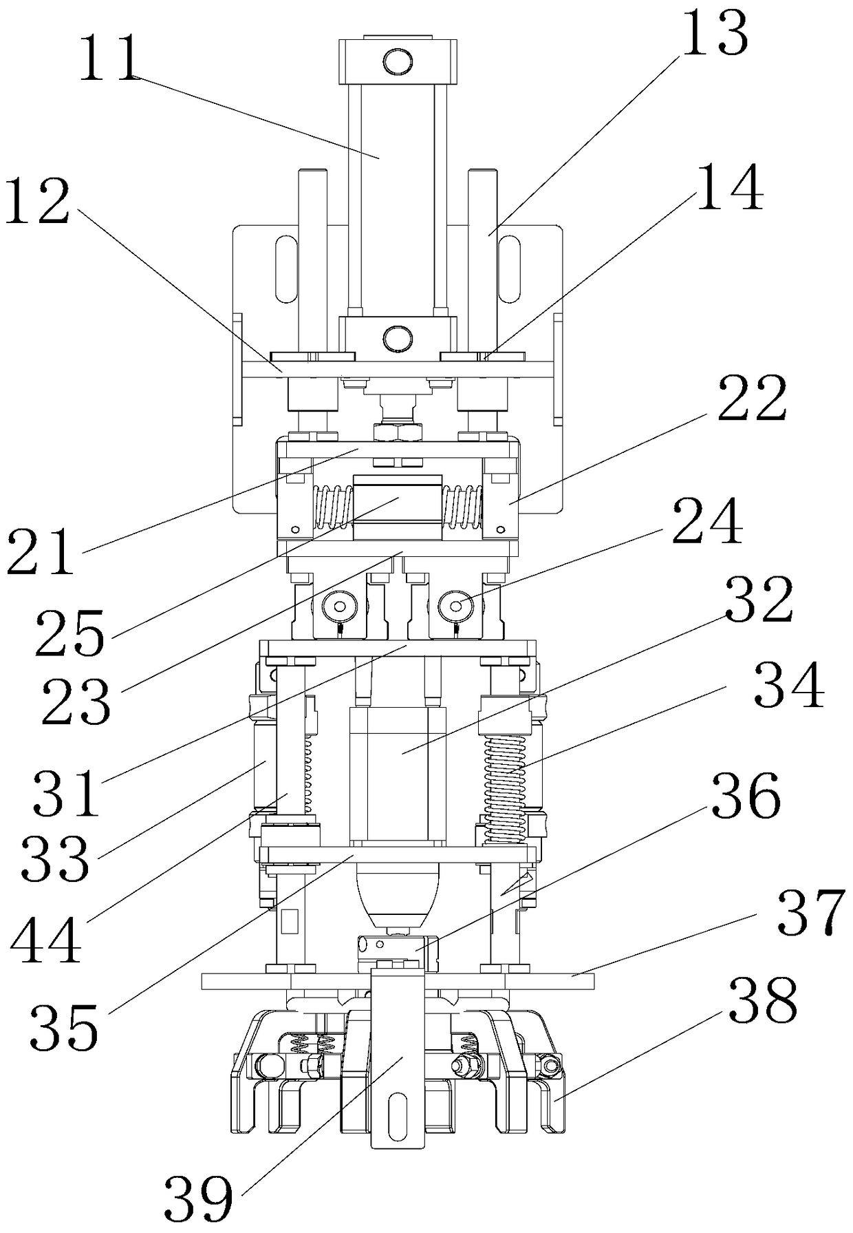
[0036] Example 1 as Figure 1 to Figure 6 As shown, the automatic capping machine of this embodiment includes a main machine, a lifting assembly 1 for the vertical displacement of the main machine arranged in sequence from top to bottom, a displacement assembly 2 for controlling the front and rear and left and right displacements of the main machine, and a displacement assembly 2 for controlling the automatic The capping machine takes the cap and the capping assembly 3 of the capping, the lifting assembly 1 and the displacement assembly 2 are connected through multiple sets of linear guide rails 13 and linear bearings 14, and the bottom of the displacement assembly 2 is fixedly connected with the top of the screwing assembly 3 .

[0037] Lifting assembly 1 comprises mounting frame 12 and lifting cylinder 11, and the center of mounting frame 12 is provided with through hole, and the output shaft of lifting cylinder 11 passes through hole and reciprocates; , the middle part of ...


PUM


Abstract

The invention relates to an automatic capping machine and a working method thereof. The automatic capping machine comprises a main machine, a lifting assembly, a displacement assembly and a capping assembly. The lifting assembly is connected with the displacement assembly through cooperation of a plurality of groups of linear guide ways and linear bearings. The bottom of the displacement assembly is fixedly connected with the top of the capping assembly, and the displacement assembly is used for transmitting motive power to control the capping assembly to move front and back or left and right. The capping assembly comprises a pneumatic motor, a plurality of capping claws and a claw seat. Each capping claw is in a shape of handgun, the middle of each capping claw is provided with a hinge joint hole, the capping claws are disposed on the outer side of the edge of the claw seat in a hinge joint and matched mode through the corresponding hinge joint holes and pin shafts, the heads of the multiple capping claws are perpendicularly disposed on the outer side of the lower portion of the edge of the claw seat, and a clamping area of a bottle cap is formed through matching. An output shaft of the pneumatic motor is coaxial with and fixedly connected with the claw seat, and during usage, the claw seat and the capping claws are driven to rotate. The automatic capping machine is simple in structure, convenient to maintain, capable of achieving capping automatically and continuously and high in production efficiency.

Description

technical field [0001] The invention relates to the field of packaging equipment, in particular to an automatic capping machine and a working method thereof. Background technique [0002] Capping machine, also known as capping machine, capping machine or cap locking machine, is used for cap screwing and loosening equipment after plastic bottles and glass bottles are packaged. It is one of the main equipments of automatic filling production line. Some capping machines are equipped with a device for tightening the bottle cap, which tends to slide relative to the bottle cap during use, causing the bottle cap to not be tightened tightly, the positioning is not accurate, etc., and the phenomenon of crooked caps is likely to occur during the clamping process. And the problem of not being able to accurately control the capping strength leads to either insufficient or over-tightening of the cap. At the same time, the labor intensity is high, the capping speed is slow, the work effic...

Claims


Application Information

Patent Timeline
Patent Type & Authority Patents(China)
IPC IPC(8): B67B3/20
Inventor 邱弘珂储立新顾建国徐涛
Owner CHANGZHOU TONY PACK WEIGHING SYST CO LTD
Learn More