Rail vehicle coupler mounting device

A coupler installation, rail vehicle technology, applied in the direction of railway vehicle coupling accessories, transportation and packaging, railway car body parts, etc., can solve the problems of low labor efficiency, low reliability, harsh working environment, etc., and achieve convenient disassembly and installation , Guaranteed passability, ingeniously designed effect

Active Publication Date: 2018-11-27
CHANGZHOU RUITAI ENG MASCH CO LTD +1
View PDF6 Cites 0 Cited by
  • Summary
  • Abstract
  • Description
  • Claims
  • Application Information

AI Technical Summary

Problems solved by technology

[0003] In the prior art, the coupler on the road-rail vehicle usually adopts a central pin device for rigid coupling, which leads to the fact that the coupled vehicle cannot offset the longitudinal impact caused by the collision of the coupler during operation, and the working environment is harsh and the reliability is low
In addition, road-rail vehicles are usually connected by bolts set at different heights to adjust the height of the coupler. The labor efficiency is low, and it is impossible to adjust the height of the coupler accurately according to the wear of the vehicle wheels.

Method used


Image

  • Rail vehicle coupler mounting device
  • Rail vehicle coupler mounting device
  • Rail vehicle coupler mounting device

Examples


Embodiment 1

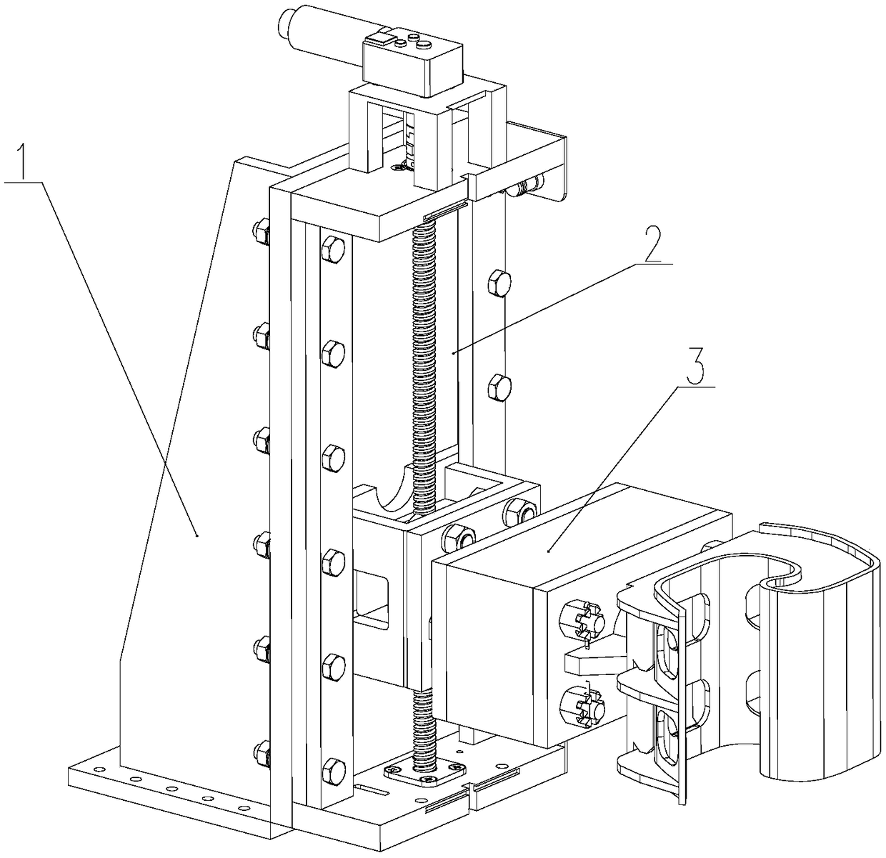
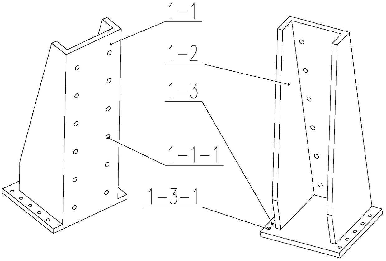
[0029] The rail vehicle coupler mounting device of the present embodiment has a structure such as figure 1 As shown, it is mainly composed of a fixing base 1, a lifting mechanism 2 and a buffer 3, the fixing base 1 is used for installing the lifting mechanism 2, and the lifting structure 2 is connected with the buffer 3. Wherein, the fixed seat 1 includes a first vertical plate 1-1, two rib plates 1-2 and a rectangular bottom plate 1-3, and the first vertical plate 1-1 and the two rib plates 1-2 are vertically arranged on the bottom plate 1. -3, and two ribs 1-2 are vertically fixedly connected to the left and right sides of the first vertical plate 1-1, and two groups of first installation holes 1 are formed on the first vertical plate 1-1 along its length direction -1-1, a group of second mounting holes 1-3-1 are respectively formed on both sides of the bottom plate 1-3, and a second bolt is provided in cooperation with the second mounting hole 1-3-1, through which the The ...

Embodiment 2

[0036] The difference between this embodiment and Embodiment 1 is that the buffer block 3-3 adopts a rubber part in the shape of a cuboid as a whole, without front and rear end plate structures, and the front end of the buffer block 3-3 passes through the front connecting rod 3-2. 1. The second connection plate 3-1 is connected with the first connection plate 2-9-3 of the buffer connection seat 2-9, and the rear end surface of the buffer block 3-3 is connected with the hook head 3 of different types through the rear connection rod 3-4 -8 connection, at the four corners of the buffer block 3-3, there are through holes through the front and rear ends of the buffer block 3-3 respectively, and a force guide rod 3-5 is arranged in the through hole, and the front end of the force guide rod 3-5 has a guiding force The rod cap 3-5-3, and the force guide rod cap 3-5-3 is in contact with the front end surface of the buffer block 3-3, the rear end of the force guide rod 3-5 has an externa...


PUM


Abstract

The invention relates to a hook installation device of a rail vehicle. The hook installation device of the rail vehicle is mainly composed of a lifting mechanism and a buffer. The lifting mechanism comprises a ball screw and a stepping motor driving the ball screw to rotate. The two ends of the ball screw are installed on an upper fixing seat and a lower fixing seat correspondingly. The upper fixing seat and the lower fixing seat are vertically arranged at the upper end and the lower end of a rear vertical plate. Two guide rails distributed in the length direction of the rear vertical plate are arranged on the rear vertical plate. A buffer connecting seat is arranged between the two guide rails. The buffer comprises a buffer block, penetrating holes penetrating through the front end and the rear end of the buffer block are formed in the four corners of the buffer block, and force guide rods are arranged in the penetrating holes in a matched mode. The hook installation device of the rail vehicle has the advantages of being ingenious in design, convenient to dismount and mount, capable of bearing collision impact of hooks, and capable of being flexibly adjusted in installation position according to the requirements of wheel pair abrasion, stress conditions and the like.

Description

technical field [0001] The invention relates to a coupler mounting seat, in particular to a rail vehicle coupler mounting device, which belongs to the field of vehicle body structure design. Background technique [0002] At present, road-rail vehicles usually need to meet the requirements for connecting with standard couplers such as locomotives and urban rail trains. Connected with trains such as subways, high-speed trains, and locomotives, and complete shunting and rescue tasks within the road bureau section, vehicle factories, and railways. [0003] In the prior art, the couplers on road-rail vehicles usually use a center pin device for rigid coupling, resulting in that the coupled vehicles cannot offset the longitudinal impact caused by the collision of the couplers during operation, and the working environment is harsh and the reliability is low. In addition, road-rail vehicles are usually connected by bolts set at different heights to adjust the height of the coupler,...

Claims


Application Information

Patent Timeline
Patent Type & Authority Patents(China)
IPC IPC(8): B61G7/10
CPCB61G7/10
Inventor 陈建姚雪松郭勐耿路峰
Owner CHANGZHOU RUITAI ENG MASCH CO LTD
Why Eureka
Try Eureka