
Electromagnetic mechanical paw with adjustable clamping force and application method thereof

A mechanical claw and electromagnetic technology, applied in the field of robotics, can solve the problems of high cost, poor control of grasping force, and low efficiency, and achieve the effects of fast response, improved operating efficiency, and reduced occupied volume

Active Publication Date: 2017-03-22
SHANDONG UNIV OF SCI & TECH
View PDF7 Cites 22 Cited by
  • Summary
  • Abstract
  • Description
  • Claims
  • Application Information

AI Technical Summary

Problems solved by technology

[0005] In order to avoid the disadvantages of the above-mentioned prior art, the present invention provides an electromagnetic mechanical gripper whose gripping force can be automatically adjusted and its application method, so as to solve the problem that the existing pneumatic gripper needs to carry an air pump, and the gripping force is not enough. Good control, low efficiency and high cost

Method used


Image

  • Electromagnetic mechanical paw with adjustable clamping force and application method thereof
  • Electromagnetic mechanical paw with adjustable clamping force and application method thereof
  • Electromagnetic mechanical paw with adjustable clamping force and application method thereof

Examples


Embodiment Construction

[0030] The present invention will be further described in detail below in conjunction with the accompanying drawings and specific embodiments, but the present invention is not limited to these embodiments.

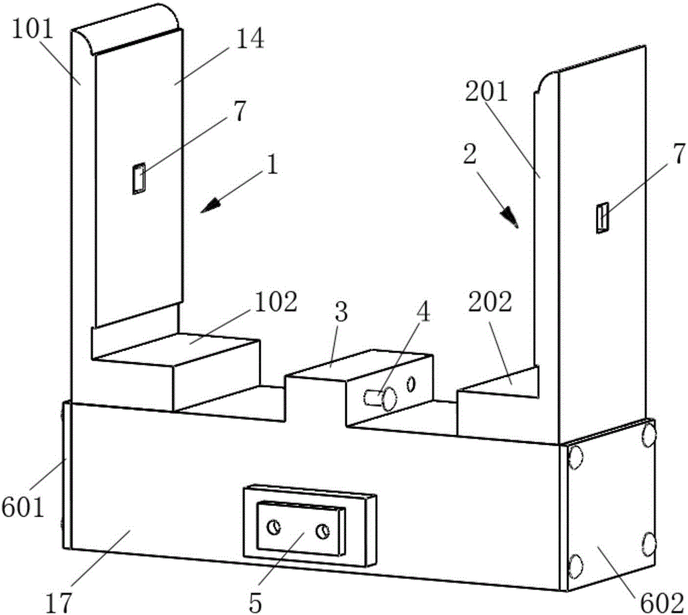
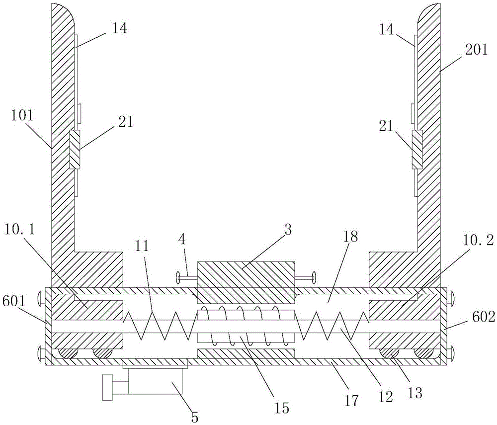
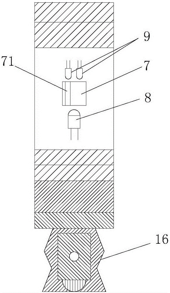
[0031] Such as Figure 1 to Figure 4 As shown, an electromagnetic mechanical gripper with adjustable clamping force includes a left gripper 1, a right gripper 2, a left permanent magnet 10.1, a right permanent magnet 10.2, an electromagnet 15, a single-chip microcomputer and a power supply for the electromagnet 15. The electromagnet power supply line. The single-chip microcomputer is connected with the electromagnet power supply line, and the current size on the electromagnet power supply line is adjustable.

[0032]The electromagnetic mechanical gripper also includes a base 17 on which the left and right grippers are installed respectively, and the electromagnet 15 is arranged in the base 17 . The base 17 is a sealed structure, which can effectively play the role of dus...


PUM


Abstract

The invention discloses an electromagnetic mechanical paw with adjustable clamping force. The electromagnetic mechanical paw comprises a left paw, a right paw, a left permanent magnet, a right permanent magnet, an electromagnet, a single chip microcomputer and an electromagnet power supply circuit, wherein the left paw and the right paw are connected, have the same structure and are in bilateral symmetry; the left permanent magnet is arranged below the left paw; the right permanent magnet is arranged below the right paw; the electromagnet is arranged between the left permanent magnet and the right permanent magnet; the single chip microcomputer is connected with the electromagnet power supply circuit; and a current on the electromagnet power supply circuit can be adjusted. The invention further discloses an application method of the electromagnetic mechanical paw with adjustable clamping force. The method comprises the process of establishment of a resistance database of the electromagnetic mechanical paw and dynamic regulation in practical application. According to the electromagnetic mechanical paw, the current introduced into an electromagnet coil is controlled through changing the resistance of a programmable resistor, the grabbing clamping force of the paw can be controlled, an electromagnetic system is adopted, heavy air pumps and hydraulic devices are eliminated, and the size is decreased.

Description

technical field [0001] The invention belongs to the technical field of robots, and in particular relates to an electromagnetic mechanical gripper with adjustable clamping force and an application method thereof. Background technique [0002] At present, with the continuous development of industrial automation, the industrial robot industry is advancing rapidly. The body of the manipulator is becoming more and more perfect, but the manipulator end effectors for different purposes need to be further developed. Most of the existing mechanical grippers have the following problems: the power is mostly pneumatic, the noise is large, and the air pump needs to be carried, and the structure is cumbersome; The gripping force is different. If the force is too small, the object will easily slip, and if the force is too large, the object will be deformed, causing damage to the object body and waste of resources. [0003] The patent application with application number 201510092211.7 dis...

Claims


Application Information

Patent Timeline
IPC IPC(8): B25J15/06B25J19/02
CPCB25J15/0608B25J19/021
Inventor 刘志海杜树坚曾庆良高正中张媛媛张鑫王亮高魁东万丽荣王成龙薛媛周晨张丹丹
Owner SHANDONG UNIV OF SCI & TECH
Learn More