A friction manipulator

A technology of manipulators and friction wheels, which is applied in the direction of manipulators, program-controlled manipulators, conveyor objects, etc., can solve the problems of cumbersome operation and low efficiency, and achieve the effect of simple design mechanism, improved efficiency and reduced physical labor

Active Publication Date: 2019-01-04
KUNMING UNIV OF SCI & TECH
View PDF7 Cites 0 Cited by
  • Summary
  • Abstract
  • Description
  • Claims
  • Application Information

AI Technical Summary

Problems solved by technology

[0003] The purpose of the present invention is to provide a friction manipulator to solve the problems of low efficiency and cumbersome operation when grabbing objects manually.

Method used


Image

  • A friction manipulator
  • A friction manipulator
  • A friction manipulator

Examples


Embodiment 1

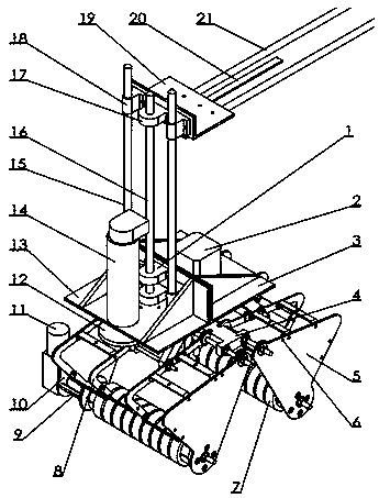
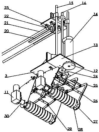
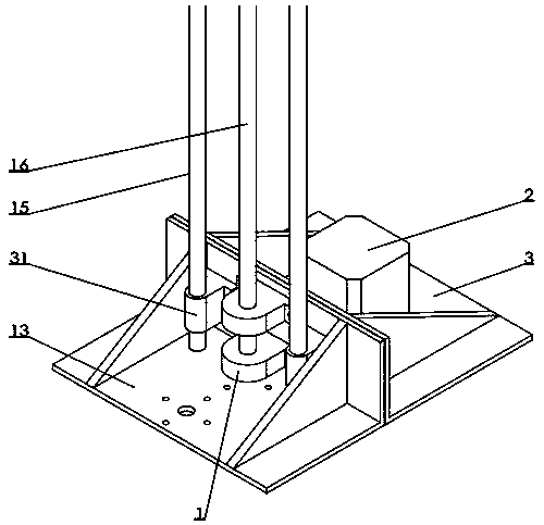
[0025] Embodiment 1: as Figure 1-9As shown, a friction manipulator includes a bearing seat 1, a motor I2, a fixed plate I3, a two-axis fixed piece 4, a baffle plate 5, a screw 6, a friction device 7, a connecting rod I8, a large gear 12, a fixed plate III13, and a motor Ⅲ14, guide rod Ⅰ15, screw rod Ⅰ16, screw nut Ⅰ17, guide rod connector 18, fixing plate Ⅳ19, belt 20, guide rod Ⅱ21, guide fixing seat 22, pulley fixing seat 23, pinion gear 24, connecting rod Ⅱ25, Connecting piece 26, connecting rod screw 29, guide rod I fixing seat 31, pulley 32, pulley shaft 33, fixing plate screw 34, major axis 35, nut 36, connecting rod connecting piece 37, short axis 38, fixing plate I connecting piece 39. Coupling Ⅱ40, bearing Ⅰ41, screw rod Ⅱ44, screw nut Ⅱ45; fixed plate Ⅰ3, fixed plate Ⅲ13 are connected by fixed plate screw 34, bearing seat 1 is installed on fixed plate Ⅲ13, motor Ⅰ2 is installed on fixed plate Ⅰ3 In the middle, the motor III14 is installed on the fixed plate III13, ...


PUM


Abstract

The invention relates to a friction mechanical arm and belongs to the technical field of mechanical robots. The friction mechanical arm comprises a bearing pedestal, a motor I, a fixing plate I, a two-axis fixing piece, baffles, screws, friction devices, a connecting rod I, a big gear wheel, a fixing plate III, a motor III, guiding rods I, a lead screw I, a lead screw nut I, guiding rod connecting pieces, a fixing plate IV, a belt, guiding rods II, a guiding fixing base, a belt wheel fixing base, a small gear wheel, a connecting rod II, a connecting piece, a connecting rod screw, guiding rod I fixing bases, a belt wheel, a belt wheel shaft, a fixing plate screw, a long shaft, a nut, a connecting rod connecting piece, a short shaft, a fixing plate I connecting piece, a coupler II, a bearing I, a lead screw II and a lead screw nut II. According to the friction mechanical arm, the efficiency of the mechanical arm in the practical application can be improved; the labor cost of manpower is saved; the mechanical mechanism and the design mechanism are simple and easy to machine; the physical labor of people can be lowered; and the friction mechanical arm can grab more spherical objects compared with manual operation, and the working efficiency can be improved.

Description

technical field [0001] The invention relates to a friction manipulator, which belongs to the technical field of mechanical robots. Background technique [0002] With the rapid development of the economy and the continuous improvement of people's living standards, the application fields of manipulators are becoming wider and wider. When picking objects, the number of manual grasping is small and some bending movements are performed repeatedly, which makes the manual operation too cumbersome; although the current application fields of manipulators are extensive, there is still room for development in grasping objects. To meet the specific needs of the occasion, a new type of manipulator that uses friction to grab and place objects is designed to grab and put some items, reduce the time of manually grabbing objects, improve the efficiency of grabbing objects, and realize the multi-function of the manipulator. change. For example, more and more people choose to play golf. Duri...

Claims


Application Information

Patent Timeline
Patent Type & Authority Patents(China)
IPC IPC(8): B25J9/00B25J15/00B65G47/90
CPCB25J9/00B25J15/00B65G47/90
Inventor 王娟代进伦王楠
Owner KUNMING UNIV OF SCI & TECH
Why Eureka
Try Eureka