Stud welding error preventing mechanism

A stud welding, error-proof technology, applied in welding equipment, welding accessories, arc welding equipment, etc., to achieve the effect of high work efficiency, simple structure and convenient operation

Inactive Publication Date: 2017-03-22
CHERY AUTOMOBILE CO LTD
View PDF5 Cites 0 Cited by
  • Summary
  • Abstract
  • Description
  • Claims
  • Application Information

AI Technical Summary

Problems solved by technology

[0004] The purpose of the present invention is to propose a stud welding error prevention mechanism, which can effectively solve the problem of stud welding error prevention in the actual production process, and is simple and convenient to operate, can reduce the problem of operator welding errors, and improve Work efficiency, save man-hours, can well respond to the differentiated needs of different models

Method used


Image

  • Stud welding error preventing mechanism
  • Stud welding error preventing mechanism
  • Stud welding error preventing mechanism

Examples


Embodiment 1

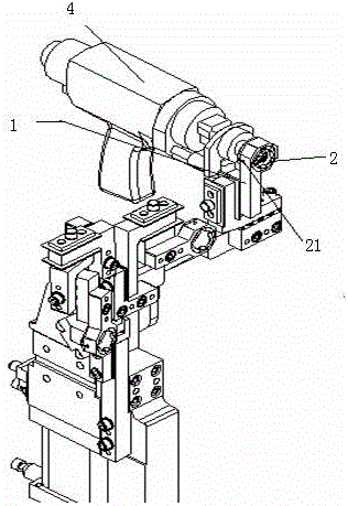
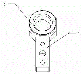
[0023] As a preferred embodiment, such as Figure 4 As shown, the rotation fulcrum 30 of the error-proof cover 3 is set on the opening edge of the stud guide sleeve 2, and the error-proof cover 3 is provided with a handle 31 for pulling the error-proof cover 3 to rotate. The worker manually pulls the handle 31 to drive the error-proofing cover 3 to rotate to the opening of the stud guide sleeve 2 to complete simple and reliable manual operation to complete the error-proofing of the stud welding. Preferably, the error-proof cover plate 3 is a circular plate adapted to the shape of the opening of the stud guide sleeve 2, and the handle 31 and the rotation fulcrum 30 are respectively arranged at both ends of the same diameter of the circular plate. Such a structure not only realizes stud welding error-proofing through the error-proof cover plate 3 that can completely cover the opening of the stud guide cylinder 2, and avoids the magnetic force leaking out of the stud welding gun ...

Embodiment 2

[0025] As another preferred embodiment, such as Figure 5 , 6 As shown, the error-proof cover plate 3 is connected to the rotary cylinder 5 , and the rotating shaft 51 of the rotary cylinder 5 is parallel to the axial direction of the stud guide sleeve 2 . This embodiment is for automatic operation and error prevention. In actual use, only the assembly and movement space of the rotary cylinder needs to be reserved on the traditional stud welding guide mechanism 1, and the error prevention cover 3 is fixedly connected with the rotating shaft 51 of the rotary cylinder 51. , and then control the rotation of the rotary cylinder 5 through an integrated circuit, and control the rotation of the rotary cylinder 5 arranged at a station that does not require stud welding according to the difference of the vehicle type, and drive the error-proof cover 3 to block the opening of the stud guide sleeve 2 At this point, automatic stud welding error prevention can be completed. This kind of ...


PUM


Abstract

The invention provides a stud welding error preventing mechanism capable of effectively solving the difficulty of stud welding error prevention in actual production process, simple and convenient to operate and capable of preferably dealing with the difference demands of different vehicle types when reducing the operator welding error problem, improving the working efficiency and saving the labor hours. The stud welding error preventing mechanism comprises a stud welding guide mechanism; and a stud guide sleeve is arranged on the stud welding guide mechanism. The stud welding error preventing mechanism further comprises an error preventing cover plate; and the error preventing cover plate is rotationally arranged at the end part of the guide sleeve, and can stop an opening of the guide sleeve through rotation. As the stud guide sleeve is added on a traditional stud welding guide mechanism, and the error preventing cover plate capable of rotating to stop the opening of the guide sleeve is added at the end part of the stud guide sleeve, workers can rotate the error preventing cover plate to the opening of the guide sleeve in a station of not needing stud welding according to the vehicle type demands to stop the stud welding so as to finish the stud welding error prevention.

Description

technical field [0001] The invention relates to the field of welding tooling technology, in particular to a stud welding error prevention mechanism. Background technique [0002] With the rapid development of the automobile industry, consumers have higher and higher requirements for vehicle configurations. For automobile companies, it is necessary to continuously develop various counterweights to meet the needs of consumers in the market. However, this requirement is currently more due to the large difference in stud welding. For the body-in-white assembly, it faces various differences, which adds great difficulty to the production line. Operators need to follow the requirements of the body-in-white. For targeted stud welding, stud welding confusion often occurs. So far, the problem of stud welding error prevention has become a difficult problem in the production process of the welding workshop. The error-proofing method used in the production process of the traditional bo...

Claims


Application Information

Patent Timeline
IPC IPC(8): B23K9/32B23K9/20
CPCB23K9/32B23K9/20
Inventor 李智阿杨桂芝盛宏志
Owner CHERY AUTOMOBILE CO LTD
Why Eureka
Try Eureka