Plate shearing machine capable of assisting feeding and discharging

A shearing machine, material feeding and discharging technology, applied in the direction of shearing equipment, shearing devices, shearing machine accessories, etc., can solve the problem that there is no positioning device, the length of the feeding bracket is limited, and it cannot meet the needs of long-length plates. Material requirements and other issues, to achieve the effect of improving shearing accuracy, stable feeding and discharging

Inactive Publication Date: 2017-03-22
重庆光明消防设备厂
View PDF0 Cites 5 Cited by
  • Summary
  • Abstract
  • Description
  • Claims
  • Application Information

AI Technical Summary

Problems solved by technology

[0003] For the convenience of use, there is a feed bracket on the side of the feed port of the shearing machine. Although it can ensure the stability of the plate feeding to a certain extent, due to the limited length of the feed bracket, it cannot meet the requirements of long lengths. The feed requirements of the sheet
And for plate shearing, it is necessary to cut the plate according to the set length, and the existing shearing machine does not have a corresponding positioning device

Method used


Image

  • Plate shearing machine capable of assisting feeding and discharging
  • Plate shearing machine capable of assisting feeding and discharging
  • Plate shearing machine capable of assisting feeding and discharging

Examples


Embodiment Construction

[0019] The present invention will be further described below in conjunction with the accompanying drawings and specific embodiments, so that those skilled in the art can better understand the present invention and implement it, but the examples given are not intended to limit the present invention.

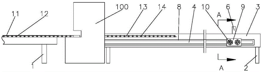
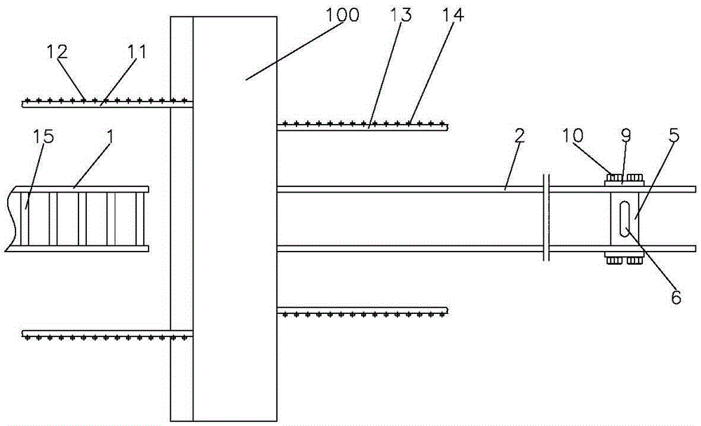
[0020] Such as figure 1 Shown is a schematic structural view of an embodiment of a shearing machine with feeding and discharging assistance in the present invention. The shearing machine with feeding and discharging assistance in this embodiment includes a shearing machine body 100, and the front and rear sides of the shearing machine body 100 are respectively provided with a sheet material feeding auxiliary mechanism and a sheet material discharging auxiliary mechanism;

[0021] The sheet material feeding auxiliary mechanism in this embodiment includes a feeding frame 1, on which conveying rollers 15 for conveying sheet materials are arranged at intervals. The auxiliary mechanis...


PUM


Abstract

The invention discloses a plate shearing machine capable of assisting feeding and discharging. The plate shearing machine capable of assisting the feeding and discharging comprises a plate shearing machine body, wherein a plate feeding assisting mechanism and a plate discharging assisting mechanism are correspondingly arranged at the front side and the rear side of the plate shearing machine body; the plate feeding assisting mechanism comprises a feeding rack; conveying rollers for conveying a plate are arranged at intervals on the feeding rack; the plate discharging assisting mechanism comprises a discharging rack; two baffle plates, which are vertically mounted and parallel to each other, are arranged on the discharging rack; elongated slide holes are correspondingly formed in the two baffle plates; a positioning plate which is mounted in the elongated slide holes in a slide matching manner is arranged between the two baffle plates; a positioning inserting hole is formed in the positioning plate; a positioning baffle plate is mounted on the positioning inserting hole. The plate shearing machine capable of assisting the feeding and discharging further comprises a control system; the control system comprises a controller, a contact sensor which is mounted on the positioning baffle plate, and a control circuit for controlling the plate shearing machine body to act; the controller is electrically connected with the contact sensor and the control circuit.

Description

technical field [0001] The invention relates to a shearing machine, in particular to a shearing machine provided with an auxiliary mechanism for feeding and discharging materials. Background technique [0002] The shearing machine is a machine that uses one blade to make a reciprocating linear motion relative to the other blade to cut the plate. It uses the moving upper blade and the fixed lower blade to apply shear force to the plates of various thicknesses by adopting a reasonable blade gap, so that the plates are broken and separated according to the required size. [0003] For the convenience of use, there is a feed bracket on the side of the feed port of the shearing machine. Although it can ensure the stability of the plate feeding to a certain extent, due to the limited length of the feed bracket, it cannot meet the requirements of long lengths. The feed requirements of the board. Moreover, for plate shearing, the plate needs to be cut according to a set length, but...

Claims


Application Information

Patent Timeline
Patent Type & Authority Applications(China)
IPC IPC(8): B23D33/02B23D33/10B23D15/06
Inventor 汤伟
Owner 重庆光明消防设备厂
Why Eureka
Try Eureka