
Electricity meter box

A technology for electric meter boxes and electric meters, which is applied in the field of electric meter boxes, can solve the problems of inconvenient installation of meters and various electrical components, inconvenient repair and maintenance, and easy drilling of installation holes by construction workers, so as to reduce electromagnetic signal interference and enhance electromagnetic isolation performance , Reasonable effect of regional function division

Inactive Publication Date: 2017-03-15
天津市威匡电气设备有限公司
View PDF4 Cites 2 Cited by
  • Summary
  • Abstract
  • Description
  • Claims
  • Application Information

AI Technical Summary

Problems solved by technology

[0002] The meter box is a common power supply and distribution device. The traditional meter box has a simple structure and a single function, which is not convenient for the installation of instruments and various electrical components in the meter box. The electromagnetic isolation performance is poor. At the same time, it is not convenient for later maintenance. maintenance work
[0003] The traditional meter box is usually exposed, occupying the external space, and is not beautiful; The body has been equipped with an embedded cavity to match the meter box, so the thickness of the wall is relatively thin, so it is easy to penetrate the wall by drilling installation holes along the thickness of the wall.
[0004] In addition, when drilling the installation holes, the construction workers tend to deviate from the position of the installation holes, so that the positions of the installation bolts on the wall cannot correspond to the positions of the installation holes on the meter box, resulting in the failure to install the box normally

Method used


Image

  • Electricity meter box
  • Electricity meter box
  • Electricity meter box

Examples


Embodiment Construction

[0026] The technical solutions of the present invention will be further described below in conjunction with specific embodiments.

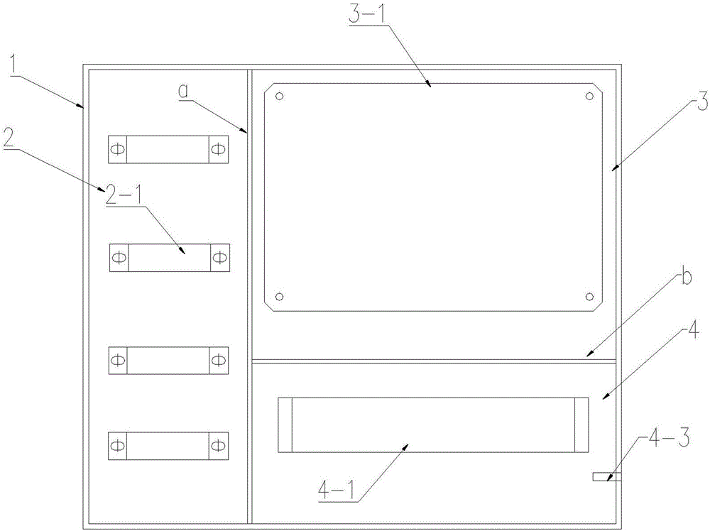
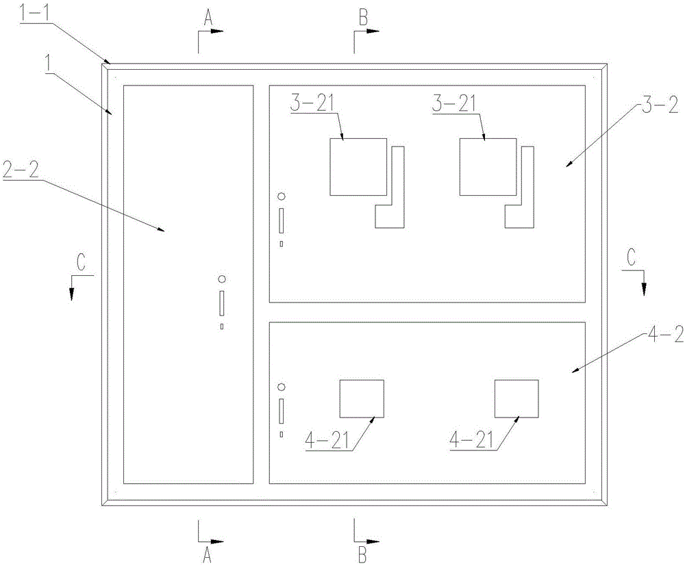
[0027] See attached Figure 1-6 , an electric meter box related to the present invention comprises a box body 1, a vertical partition a is arranged in the box body 1, and a horizontal partition b is arranged on one side of the vertical partition a, thereby dividing the box body into three Two chambers: the T connection room 2, the meter installation room 3 and the circuit breaker installation room 4; a through hole a-1 is opened on the vertical partition a, and a through hole b-1 is opened on the horizontal partition b , the through hole a-1 and the through hole b-1 are used for the penetration of wiring cables;

[0028] A plurality of T-bar brackets 2-1 for fixing the T-bars are arranged in the T-bar room 2; a wooden installation base plate 3-1 for installing the electric meter is arranged in the meter installation room 3, and the wooden install...


PUM


Abstract

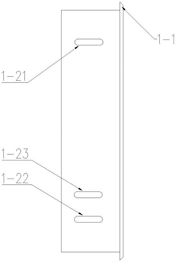
The invention discloses an electricity meter box, which comprises a box body, wherein the box body is divided into three chambers, namely a T connection bar chamber, an electricity meter installation chamber and a circuit breaker installation chamber; a plurality of T connection bar brackets for fixing T connection bars are arranged in the T connection bar chamber; a wood installation bottom plate for installing an electricity meter is arranged in the electricity meter installation chamber; a rack for installing a circuit breaker and a ground pole are arranged in the circuit breaker installation chamber; the box body is provided with a T connection bar chamber door body matched with the T connection bar chamber, an electricity meter installation chamber door body matched with the electricity meter installation chamber and a circuit breaker installation chamber door body matched with the circuit breaker installation chamber; viewing windows are arranged in the electricity meter installation chamber door body and the circuit breaker installation chamber door body; a circle of outline shielding edge is arranged on the outline of the box body; installation through holes are arranged in two side surfaces of the box body and are elongated through holes, so that a constructor adjusts the vertical embedded depth position of installing the box body; and three installation through holes are arranged in each side surface.

Description

technical field [0001] The invention belongs to the technical field of distribution boxes, in particular to an electric meter box. Background technique [0002] The meter box is a common power supply and distribution device. The traditional meter box has a simple structure and a single function, which is not convenient for the installation of instruments and various electrical components in the meter box. The electromagnetic isolation performance is poor. At the same time, it is not convenient for later maintenance. maintenance work. [0003] The traditional meter box is usually exposed, occupying the external space, and is not beautiful; The body has been equipped with an embedded cavity to match the meter box, so the thickness of the wall is relatively thin, so it is easy to penetrate the wall by drilling installation holes along the thickness of the wall. [0004] In addition, when drilling the mounting holes, the construction workers tend to deviate from the position o...

Claims


Application Information

Patent Timeline
Patent Type & Authority Applications(China)
IPC IPC(8): H02B1/40
CPCH02B1/40
Inventor 黄文荣
Owner 天津市威匡电气设备有限公司
Learn More