
Microscopic three-dimensional measuring device and system

A technology of three-dimensional measurement and object measurement, applied in the field of three-dimensional measurement, can solve problems such as low precision, camera failure, incomplete three-dimensional surface data of objects, etc., achieve high sensitivity and accuracy, and improve the effect of pixel utilization

Active Publication Date: 2017-03-15
SHENZHEN UNIV
View PDF11 Cites 13 Cited by
  • Summary
  • Abstract
  • Description
  • Claims
  • Application Information

AI Technical Summary

Problems solved by technology

[0002] The application of 3D technology is becoming more and more widespread. 3D images can allow us to better perceive the diversity of the real world. How to obtain 3D point cloud data of objects in a more convenient and quick way is a hot spot in the field of 3D measurement. Currently, the commonly used 3D measurement methods are based on The structured light measurement method of the triangulation principle, the general triangulation method, because the projection optical axis and the camera optical axis form a certain angle, it will be affected by the surface shape of the object, and some object surface areas can be projected by the projector. However, some cameras can capture the area, but the projector cannot project it, which eventually leads to incomplete 3D surface data of the reconstructed object. The inherent occlusion and shadow problems of this triangulation principle limit this technology. Application of method
At present, the 3D reconstruction method of light field camera is generally based on the Fourier slice theorem to analyze the 4D light field data. The tomographic picture of the changing focus area of ​​the image, and then reconstruct the three-dimensional surface shape of the object surface according to the relationship between the depth and the focus point. The accuracy depends on the number of layers of the tomography, and the relative accuracy is low

Method used


Image

  • Microscopic three-dimensional measuring device and system
  • Microscopic three-dimensional measuring device and system
  • Microscopic three-dimensional measuring device and system

Examples


Embodiment Construction

[0032] In order to make the object, technical solution and advantages of the present invention clearer, the present invention will be further described in detail below in conjunction with the accompanying drawings and embodiments. It should be understood that the specific embodiments described here are only used to explain the present invention, not to limit the present invention.

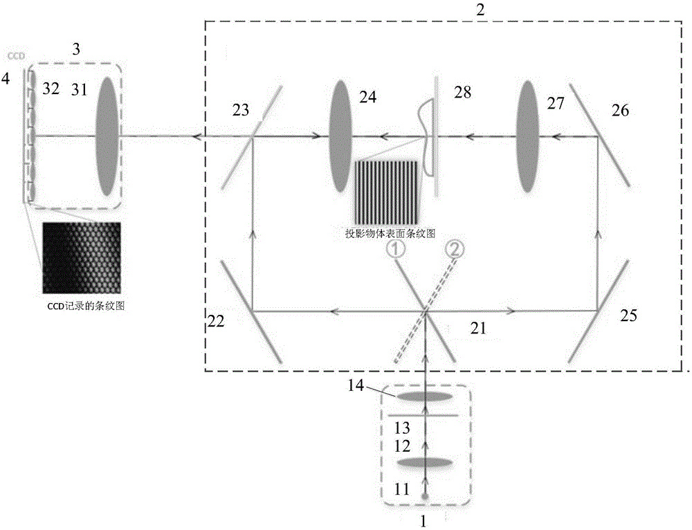
[0033] The main realization idea of ​​the present invention is: a microscopic three-dimensional measuring device and system provided by the present invention, the light emitted by a single three-dimensional coordinate point in the object space is imaged after passing through the first lens group, the half mirror and the main lens, and the light continues to The forward propagation will be captured by the CCD behind multiple microlenses to obtain recorded images. Each microlens corresponds to an N*N macro pixel, and one object space point will eventually correspond to multiple recorded image points,...


PUM


Abstract

The invention, which is applicable to the technical field of three-dimensional measurement, provides a microscopic three-dimensional measuring device and system. The device comprises a structured light generating device, an optical path steering assembly, an imaging lens group and a CCD. The structured light generating device is used for generating structured light; the optical path steering assembly is used for guiding the structured light to a to-be-measured object and guiding light carrying object image information to the imaging lens group after the light passes through the to-be-measured object. The imaging lens group consists of a main lens and a micro lens array being a light-field camera and is used for transmitting the light. The CCD is used for recording light transmitted by adjacent micro lenses in the micro lens array, thereby obtaining a recorded image. With the system and device provided by the invention, a problem of shadow shielding in structured light three-dimensional measuring can be solved. Meanwhile, on the basis of combination of the light-field camera and the structured light three-dimensional measuring, the pixel utilization rate of the light-field camera is improved substantially and the precision is high.

Description

technical field [0001] The invention belongs to the technical field of three-dimensional measurement, and in particular relates to a microscopic three-dimensional measurement device and system. Background technique [0002] The application of 3D technology is becoming more and more widespread. 3D images can allow us to better perceive the diversity of the real world. How to obtain 3D point cloud data of objects in a more convenient and quick way is a hot spot in the field of 3D measurement. Currently, the commonly used 3D measurement methods are based on The structured light measurement method of the triangulation principle, the general triangulation method, because the projection optical axis and the camera optical axis form a certain angle, it will be affected by the surface shape of the object, and some object surface areas can be projected by the projector. However, some cameras can capture the area, but the projector cannot project it, which eventually leads to incomple...

Claims


Application Information

Patent Timeline
Patent Type & Authority Applications(China)
IPC IPC(8): G01B11/25
CPCG01B11/25
Inventor 吴庆阳曾增李玲张佰春李景镇
Owner SHENZHEN UNIV
Learn More