
A lifting and rotating positioning device

A positioning device, lifting and rotating technology, used in assembly machines, workbenches, metal processing equipment, etc., to meet the needs of automated assembly operations

Inactive Publication Date: 2018-08-10
ANHUI JIANGHUAI AUTOMOBILE GRP CORP LTD
View PDF7 Cites 0 Cited by
  • Summary
  • Abstract
  • Description
  • Claims
  • Application Information

AI Technical Summary

Problems solved by technology

[0005] The purpose of the present invention is to provide a lifting and rotating positioning device to solve the problems of engine attitude adjustment and precise positioning

Method used


Image

  • A lifting and rotating positioning device
  • A lifting and rotating positioning device
  • A lifting and rotating positioning device

Examples


Embodiment Construction

[0037] The technical solution of the present invention is described in detail below through the examples, and the following examples are only exemplary and can only be used to explain and illustrate the technical solution of the present invention, rather than being interpreted as a limitation to the technical solution of the present invention.

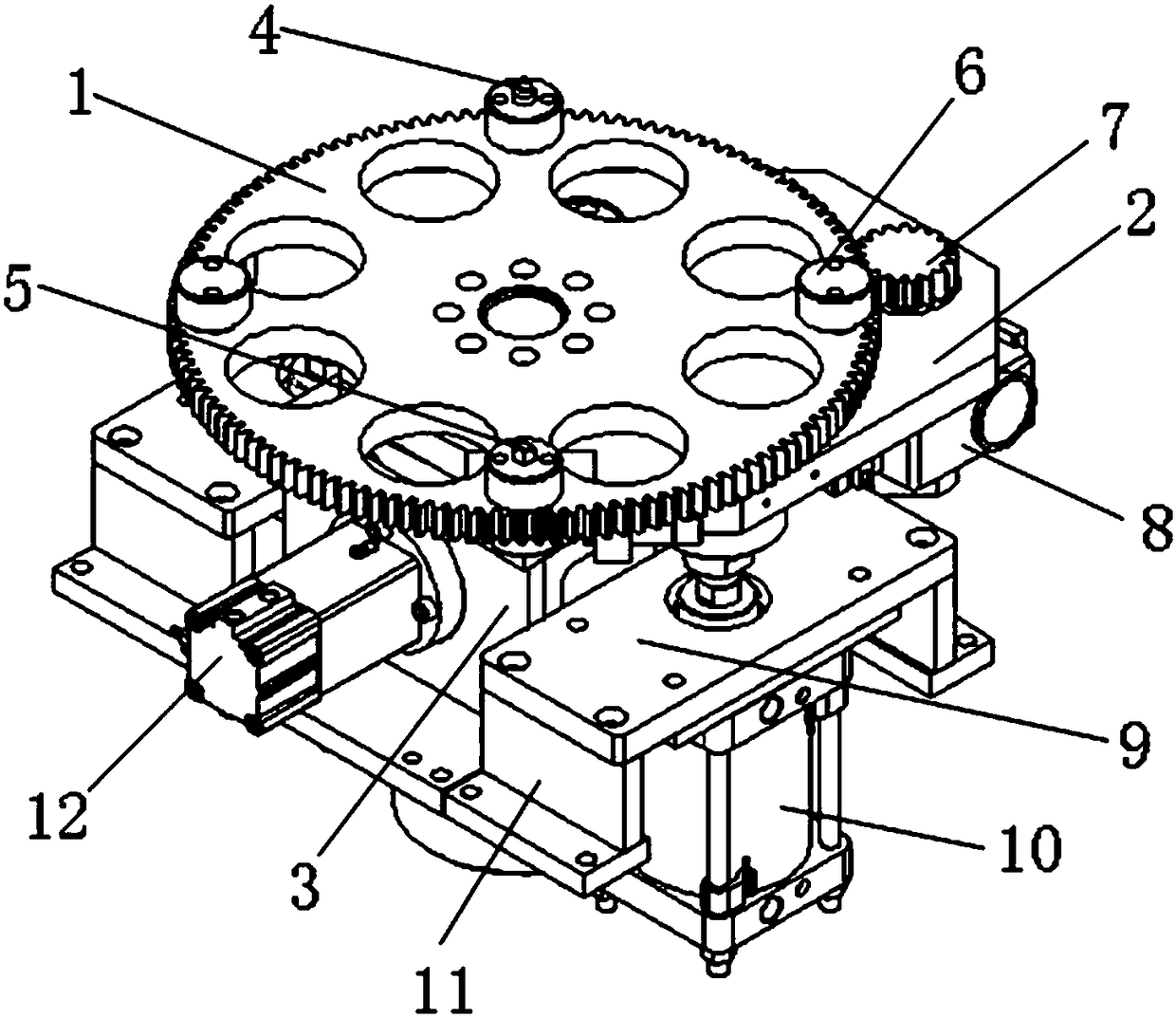
[0038] The present application provides a lifting and rotating positioning device, which includes a lifting part and a rotating part.

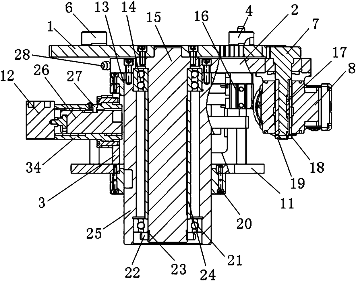
[0039] see image 3 , the lifting part is provided with a support 3, the support 3 is a weldment, a round hole is provided in the middle of the support 3, the first guide sleeve 25 passes through the support 3 and is connected to the lifting platform 2, the first guide sleeve 25 is connected to the lifting platform 2 Fastened with screws. And the upper and lower parts of the support 3 are respectively provided with a cover 13 and a cover 20, and the cover 13 and the cover 20 are fixed on the support 3...


PUM


Abstract

The invention relates to a lifting and rotating locating device which comprises a lifting part and a rotating part. The lifting part comprises a supporting seat, a first guide sleeve, a lifting table, a core shaft, a shaft sleeve, a first plug air cylinder, a movable plug, lifting air cylinders, air cylinder mounting plates and supports. The rotating part comprises a motor, a gear shaft, a gear, a second plug air cylinder, a plug, a second guide sleeve and a supporting part. According to the lifting and rotating locating device, a rotating table automatically ascends and descends through the air cylinders and is driven by the motor to automatically rotate, automatic rotating locating on an engine and a tray thereof is achieved, and the need for automatic assembly work of the engine is met.

Description

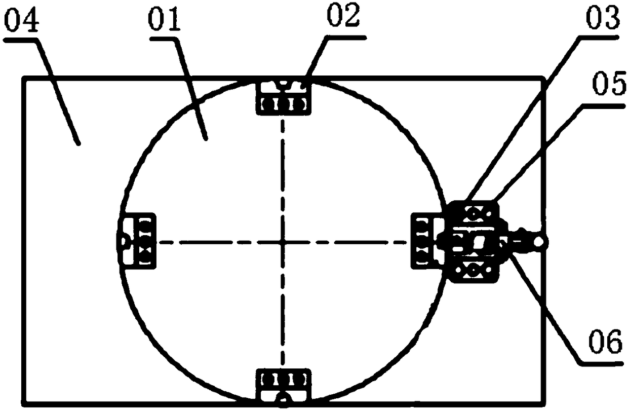
technical field [0001] The invention belongs to the technical field of engine assembly lines, in particular to a lifting and rotating positioning device. Background technique [0002] During the assembly process, the power roller table is usually used to complete the circulation and transportation of the engine. The engine tray is an indispensable support in the engine assembly line. The circulation of the engine is usually realized by the engine tray. In the actual assembly process of the engine, often Change the attitude of the engine and the pallet to meet the needs of engine assembly. In some automated assembly stations, not only the attitude of the engine needs to be changed, but also the engine needs to be precisely positioned, which is difficult to achieve through manual rotation. [0003] The rotary positioning mechanism of prior art such as figure 1 As shown, four positioning blocks 02 are evenly distributed on the upper surface of the rotary plate 01, and the oute...

Claims


Application Information

Patent Timeline
Patent Type & Authority Patents(China)
IPC IPC(8): B25H1/14B25H1/16B23P21/00
CPCB23P21/00B25H1/14B25H1/16
Inventor 曹金贵侯域唐磊胡俊德闫浩泉
Owner ANHUI JIANGHUAI AUTOMOBILE GRP CORP LTD
Learn More