
An automatic turning fixture

An automatic flip and fixture technology, applied in the direction of clamping, clamping devices, manufacturing tools, etc., can solve the problems of urgent application of functional fixtures, pinching, low processing efficiency, etc., to achieve simple structure, avoid pinching, and improve processing efficiency. Effect

Active Publication Date: 2016-02-03
TAICANG DENASEN MECHANICAL & ELECTRICAL ENG CO LTD
View PDF7 Cites 0 Cited by
  • Summary
  • Abstract
  • Description
  • Claims
  • Application Information

AI Technical Summary

Problems solved by technology

For small-batch products, one side is usually processed first, and then the other side is processed. The processing efficiency is relatively low. Emphasis on the concentration of processes, the application of functional fixtures is becoming more and more urgent

Method used


Image

  • An automatic turning fixture
  • An automatic turning fixture
  • An automatic turning fixture

Examples


Embodiment Construction

[0013] The present invention will be further described below in conjunction with accompanying drawing, protection scope of the present invention is not limited to the following:

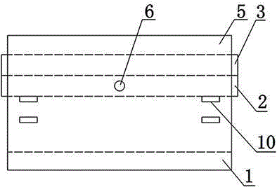
[0014] Such as figure 1 As shown, a kind of automatic turning fixture, it comprises support seat 1, turning frame 2, pressing frame 3, support plate 4, upper layer driving cylinder 11, lower layer driving cylinder 12 and rotating motor 13, the top of support seat 1 is provided with two two support plates 5 arranged in parallel, the overturning frame 2 is arranged between the two support plates 5, a rotating shaft 6 is arranged on the edge of the overturning frame 2 close to the two support plates 5, and a rotating shaft 6 is arranged on the two support plates 5 The shaft hole that matches the rotating shaft 6, the two rotating shafts 6 on the turning frame 2 are all rotatably installed in the shaft holes of the support plate 5 on the corresponding side, the upper surface of the turning frame 2 is pro...


PUM


Abstract

The invention discloses an automatic turning-over fixture. The automatic turning-over fixture comprises a supporting base (1), a turning-over frame (2), a pressing frame (3), supporting plates (4), an upper driving air cylinder (11), a lower driving air cylinder (12) and a rotating motor (13), two rotating shafts (6) on the turning-over frame (2) are respectively and rotationally arranged in a shaft hole of a support plate (5), on the corresponding side, of the supporting base (1), the pressing frame (3) is arranged on the upper surface of the turning-over frame (2), each support plate is provided with an upper row of through holes (10) and a lower row of through holes (10), an output shaft of the rotating motor (13) is connected with the rotating shafts (6), one ends of the supporting plates (4) in the through holes (10) are fixedly connected through connection plates, and the connection plates are connected with the driving air cylinders. The automatic turning-over fixture has the advantages of being simple in structure, convenient to operate, and capable of achieving two-side machining of a workpiece, improving machining efficiency and having a high degree of automation.

Description

technical field [0001] The invention relates to the technical field of machine tool auxiliary clamps, in particular to a reversible clamp. Background technique [0002] Lathe processing products are usually processed on one side and clamped again to process the other side, or products with a certain angle are positioned and clamped by tooling according to the angle, and the angle turning is realized through the fixture, and the processing is carried out in sequence, usually in multiple installments Clamping completes a part, and often a product in mass production needs to be realized on several machine tools. For small-batch products, one side is usually processed first, and then the other side is processed. The processing efficiency is relatively low. Emphasis on the concentration of processes, the application of functional fixtures is becoming more and more urgent. Contents of the invention [0003] The object of the present invention is to overcome the disadvantages o...

Claims


Application Information

Patent Timeline
Patent Type & Authority Patents(China)
IPC IPC(8): B23Q7/00
CPCB23Q1/25B23Q3/00B23Q2703/02
Inventor 唐良华
Owner TAICANG DENASEN MECHANICAL & ELECTRICAL ENG CO LTD
Learn More