Optical system

An optical system and laser technology, applied in the field of optical systems, can solve problems such as numerous operations, inaccurate capture and strike accuracy, etc., and achieve the effects of simple equipment structure, improved accuracy and reliability, and reduced design and manufacturing costs

Inactive Publication Date: 2017-03-08
LEISHEN INTELLIGENT SYST CO LTD
View PDF5 Cites 6 Cited by
  • Summary
  • Abstract
  • Description
  • Claims
  • Application Information

AI Technical Summary

Problems solved by technology

[0005] The embodiment of the present invention provides an optical system, aiming to solve the small target capturing and striking device in the prior art. The optical sy...

Method used


Image

  • Optical system
  • Optical system
  • Optical system

Examples


Embodiment Construction

[0017] In order to make the object, technical solution and advantages of the present invention clearer, the present invention will be further described in detail below in conjunction with the accompanying drawings and embodiments. It should be understood that the specific embodiments described here are only used to explain the present invention, not to limit the present invention.

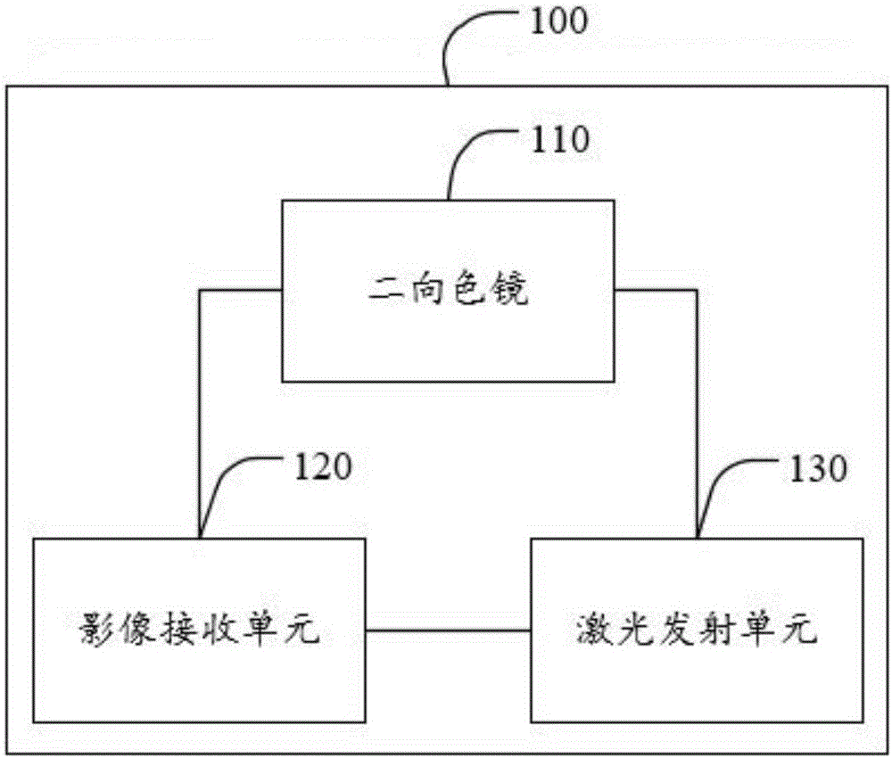
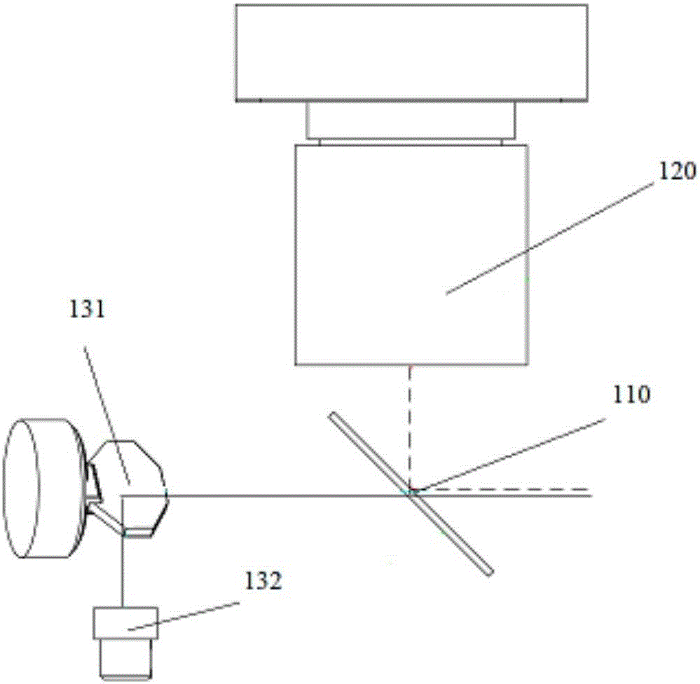
[0018] The optical system provided by the embodiment of the present invention is designed to be coaxial with the laser emitting optical axis of the laser emitting unit and the reflected light receiving optical axis of the reflected light of objects in the target range, thereby improving the accuracy and reliability of the optical system for real-time strikes; at the same time, sending and receiving The coaxial system design can make the device structure simpler, light in size, and reduce the design and manufacturing costs of lidar.

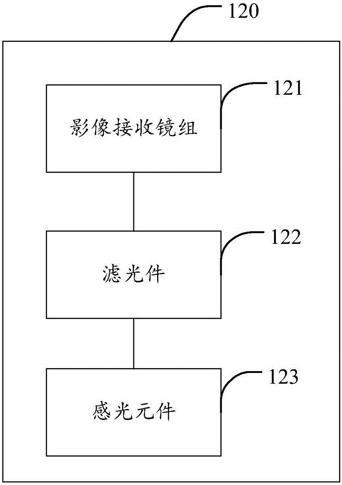
[0019] In the embodiment of the present invention, the optical sy...


PUM


Abstract

The invention relates to the field of laser optical design, and provides an optical system. The optical system comprises a dichroscope, an image receiving unit and a laser emission unit. The image receiving unit is used for receiving target range object reflected light which is reflected by the dichroscope and is provided with preset wavelength, and forming and outputting image information so as to acquire position information of a target object. The laser emission unit is used for carrying out laser emission on the target object through the dichroscope according to the position information of the target object. The laser emission optical axis of the laser emission unit is coaxial with the reflected light receiving optical axis of the target range object reflected light. According to the embodiment of the invention, through the design that the laser emission optical axis of the laser emission unit is coaxial with the reflected light receiving optical axis of the target range object reflected light, the real-time striking accuracy and reliability of the optical system are improved; and meanwhile, through a design of a transceiving coaxial system, the structure of the device is quite simple, the size is small and design and manufacturing cost of a laser radar is reduced.

Description

technical field [0001] The invention belongs to the field of laser optical design, and in particular relates to an optical system. Background technique [0002] With the development of science and technology, small target capture and attack equipment are becoming more and more intelligent, such as laser mosquito killer device, which includes a target detection module, which is used to scan and detect targets in the field of view with a cmos camera, and obtain The coordinate information of the target under the detection light path; the target strike module is used to use the coordinate information to control the strike beam to strike the target in real time. [0003] However, in the small target capture and striking device in the prior art, the optical path of its target detection module and the optical path of the striking light beam of the target strike module are on different optical paths, so that the optical system of the whole device can capture and strike the target ac...

Claims


Application Information

Patent Timeline
IPC IPC(8): G01S17/48
CPCG01S17/48
Inventor 胡小波雷祖芳巫后祥
Owner LEISHEN INTELLIGENT SYST CO LTD
Why Eureka
Try Eureka